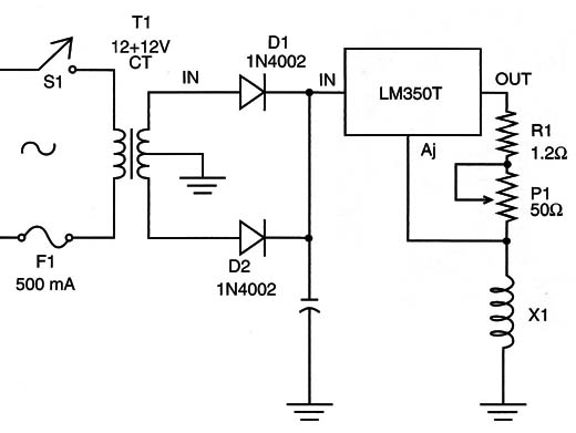
Experiments with static magnetic fields, or fields like the ones produced by magnets, can be made using the circuit shown in Figure 1.

The strength of the produced magnetic field depends on the amount of current flowing across the coil and the number of turns of the coil (See articles BM021E, BM022E and BM023E).
P1 adjusts the amount of current, and values between 100 milliamps and 1 amp are recommended.
Large values will lead to heat generation, mainly in the coil, which is the same used in the previous experiments, and the integrated circuit (IC) must be mounted on a heatsink.
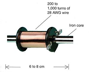
Experiments with concentrated magnetic fields can be made using an electromagnet, such as the one shown in Figure 2.

The advantage of this electromagnet is that you can control the field strength, which is not possible with common magnets. The magnet is formed by 100 to 500 turns of 28 to 32 AWG wire in a plastic tube or an iron core (a screw can be used for this task).
Magnetic Fields and Health
For many decades, research has been done to determine the influence of low-frequency magnetic fields on human health. The main focus of this research has been on the fields created by high-voltage power lines, computer monitors, and TV sets. The result of that research has revealed the dangers of such strong fields, possibly causing cancer and leukemia.
What happens is that many cells in our body have natural Vibration frequencies (due to resonance) near the frequency of the AC power line, which is 50 or 60 Hz. Under the influence of the low-frequency fields, the atoms inside the cell tend to Vibrate strongly, destroying or altering the structure of the cell.
In many countries, laws have been established to prevent homes from being built within 100 meters of any high-voltage power lines. Experiments with insects, plants, and other living things can reveal more about the influence of these fields.
IC-1: LM350T integrated circuit voltage regulator
D1, D2: 1N4002 silicon rectifier diodes
Cl: 2,200 µF x 25 V electrolytic capacitor
P1: 50 ohm wire-wound potentiometer
Rl: 1.2 ohm x 1 W wire-wound resistor
T1: Transformer, with the primary according to the power supply
line and the secondary at 12 - 12 V x 1.5 A
S1: On/off switch
Fl: 500 mA fuse and holder
X1: Coil (see text)
Other: PCB or solderless board, power cord, heatsink for the IC, wires, solder, etc.


