
In its basic application, the step motors are controlled by microprocessors and special circuits which allow to make their positioning in a precise way according to the use. The step motors scan the sensors on scanners and printers, as well as the positioning of the recording heads.
These motors operate in small increments of position that are determined by their type.
However, these motors can also operate in different ways, rotating continuously when properly polarized, and even generating electrical energy, such as a dynamo.
In this article, we'll look at some experiments which can be done with step motors.
WHERE TO GET STEP MOTORS
Nowadays there is a certain facility in obtaining used but well maintained step motors. Many dot-matrix printers and office machines that no longer work, and even other types of computer peripherals may be abandoned with their step motors in good condition.
At part stores, or even in places where there are scraps of electronic equipment and offices we have found these step motors. They are also found in stores which sell auctioned parts or even at threft shops exhibiting huge boxes full of step motors in good condition, which are sold for prices in the range of $ 1.00 to $ 10.00 according to its type.
With two motors of this type many experiences and demonstrations can be made. That's what we'll see next.
THE TYPES OF STEP MOTOR
In Figure 1 we have the most common aspects for these motors that should not be confused with DC motors.

While DC motors have only two poles or two connecting wires, the step motors have several connecting wires for a set of internal coils.
The most common type of step motor has two independent windings arranged as shown in Figure 2.

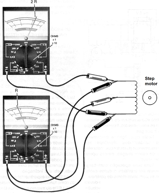
In this motor we have 6 wires of connection. The extreme and central outlets of each winding can be determined easily by measuring the resistance with a multimeter. These are the ideal motors for conducting simple experiments like the ones we describe in this article.
Thus, the first step in achieving such an engine is to identify the wires connecting the windings. The resistance between the central tap and each end should be half of the one found between the wire endings, as shown in Figure 3.
FUNCTIONING AS A DC MOTOR
In normal operation the step motors are positioned by logic signals applied on their coils.
In order for them to rotate in one direction or another it is applied sequential signals in the coils according to a certain order which depends on the type, as we have already explained in an article published in this site.
The operating voltages of these motors are usually in the range of 12 to 24 volts and their consumption, as in any type of motor, will depend on the effort they must make.
Thus, a typical 16 V motor needs only 25 mA to rotate in "no load”, i.e., with nothing attached to its axis, and will have its consumption with maximum force rising to something around 300 mA.
To turn an "no load" motor in order to demonstrate its principle of operation we do not need a high power circuit. Even with the 5 V of a TTL circuit, giving a little "help" to the match we can make a low power motor spin.
What is done then is to apply quadrature signals in the windings. The frequency of these signals will determine the speed at which it should rotate, there being a clear limit to that.
In Figure 4 we have a circuit that can rotate a step motor so that it operates as a DC motor with the speed controlled by the oscillator frequency.

In this circuit the pair of BD135/BD136 transistors with 1k2 resistors forms a source which divides the supply voltage by 2. Thus, according to the oscillator outputs going to the high or low level, the transistors conduct alternately, making the current flows in one direction or another of the motor windings.
For higher power we can add a bridge with higher power transistors such as Darlington NPN and PNP power transistors, according to the requirements of the motor.
The reader should experimentally check the combination of wires to be used in the connection to determine the direction of rotation of the motor. If one of the coil pairs is turned upside down, the motor should stop at an intermediate position of the turn.
Another interesting way to control the motor is by using two flip-flops, see an example in Figure 5.
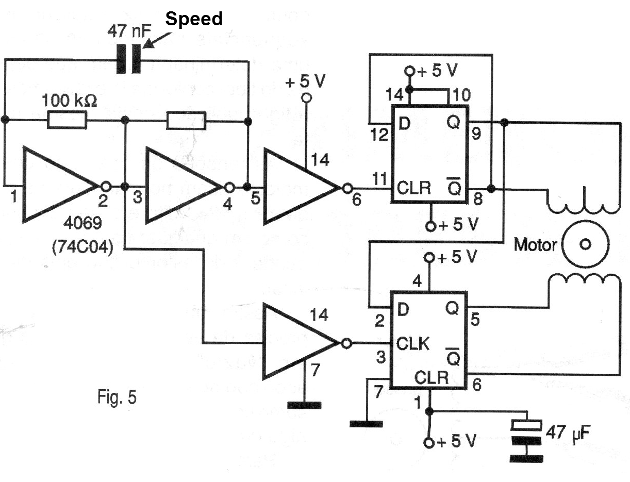
The signals applied to these flip-flops will alternately energize the windings, causing the motor to rotate. In this case, we directly connect the outputs of the flip-flops to the windings of the motor which, for demonstration purposes, must operate "empty". For a live operation, driver circuits with power transistors must be provided.
Again, the flip-flops must be driven so that the sequence of pulses applied to the windings is correct and thus fix the direction of the rotation. This can be obtained experimentally.
Note that if these flip-flops are controlled by an interface connected to the parallel port of a computer, we can generate the signals through a program by making the step motor rotate according to a speed selection per mouse.
In technical courses, stepper motor experiments can be useful to help the student understand their operation.
After an experiment in which the student is asked to discover the exact sequence required for the rotation, he/she can be asked to explain why.
USING ENGINES AS EXPERIMENTAL DYNAMOS
A first interesting experiment which can be done using an engine as a generator is shown in Figure 6.
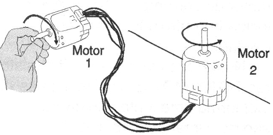
By rotating the rotor of one motor with your fingers to make it functions as a dynamo, the other motor will rotate following the movement. If the motors are of the same type, it will be easier to connect. If they are different, one must discover experimentally the combination of wires which results in this effect.
Among the possible applications in an experimental or didactic laboratory, we have the following:
a) Anemometer for the measurement of the wind speed by the generated voltage. Just plug a voltmeter into the outlet. A wind speed chart can be drawn from experiments made with a silk thread by its slope.
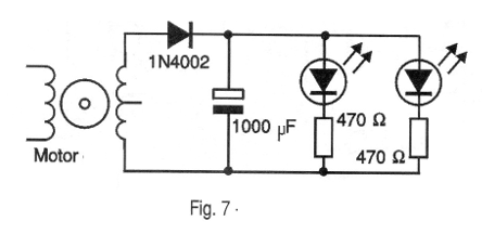
b) Experimental dynamo showing how a hydroelectric plant works. LEDs or
c) even small low-power lamps can be connected by the energy generated by a simple stepper motor, as suggested in Figure 7.
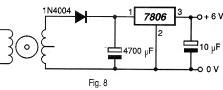
d) By connecting a full-wave rectifier circuit and a voltage stabilizer, a dynamo can be made to power small electronic devices such as transistor radios, calculators, clocks, flags, a small LASER pointer, etc. In Figure 8 we show a rectifier circuit with an integrated voltage regulator which can be used for this purpose.
e) Experiments such as the charge of capacitors with the energy generated by the motor can be planned.


