Common sequential systems with a 4017 integrated circuit or other counters have a serious drawback: we can adjust the entire cycle time at will, but we can not adjust the outputs so that they remain activated for different times.
This type of application is necessary in systems such as traffic lights, where red and green must have different duration from yellow, in presence simulators and even in the automation of industrial machines.
With the circuit that we propose this problem is solved, which opens up a range of many practical applications: each output can be programmed for a drive in a range that goes from a fraction of second to nearly one hour, and the number of outputs, basically given as 3, can be expanded indefinitely, always with the same behavior.
The circuit is relatively simple, using a 555 integrated and with control relays it can control loads of different characteristics.
HOW IT WORKS
The base of the circuit is the 555 timer which functions as a monostable multivibrator in this application.
The 555 are cascaded so that disabling each causes the next to be activated.
As we know, the 555 triggering in the monostable configuration is done by momentarily grounding the input 2 that is under positive voltage, thanks to a 33 k resistor connected to the power supply (+ B).
To initiate the sequencing process, a pressure switch lands the first port 2 of the integrals 555.
At this time, the output 3 of this first integrated is brought to the HI level, energizing the first relay which feeds its load.
The time period at this output will remain at the HI level which depends on the time constant given by P1/R2/C3. A table, shown in Figure 1, allows you to change the time periods according to the applications.
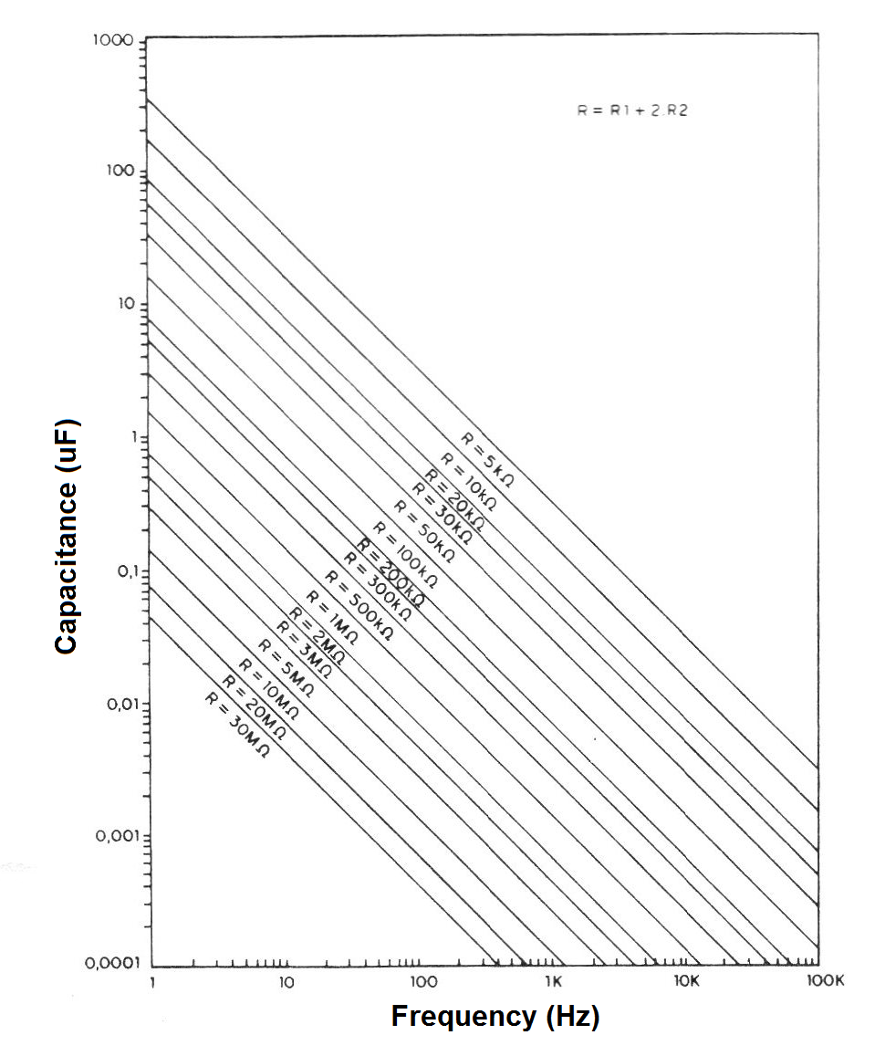
It should be noted that the total resistance in the time circuit must not be less than 1 k and not more than 1 M and that the capacitance can not be less than 100 pF nor more than 470 uF.
When the output of pin 3 of the first integrated returns to the LO level, the capacitor C4 is short-circuited so as to apply the triggering signal to the second integrated (Cl-2) on its pin 2.
This integrated is then energized, so that the relay on its output activates.
The activation time of this integrated is given by the time constant P2/R4/CS, through the same process of the previous step.
Subsequently, the following stages are triggered with the deactivation of each relay, as shown in Figure 2.
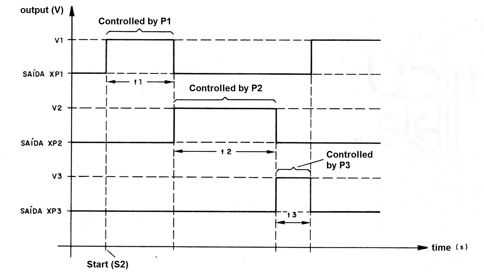
In the original design we give only 3 activation stages, at the end the feedback (C2), which restarts the process. Nothing prevents further stages from being added to other types of applications.
The relays used can feed loads of currents up to 4A (pairs of contacts connected in parallel), but the use of larger current relays is also feasible.
Likewise, NF contacts can be used to disable loads at the desired time periods.
The supply of the circuit is made by a very simple source, which provides a voltage around 12 V, with an indicator LED to monitor the operation of the device.
ASSEMBLY
In Figure 3 we give the complete circuit of the automation device.
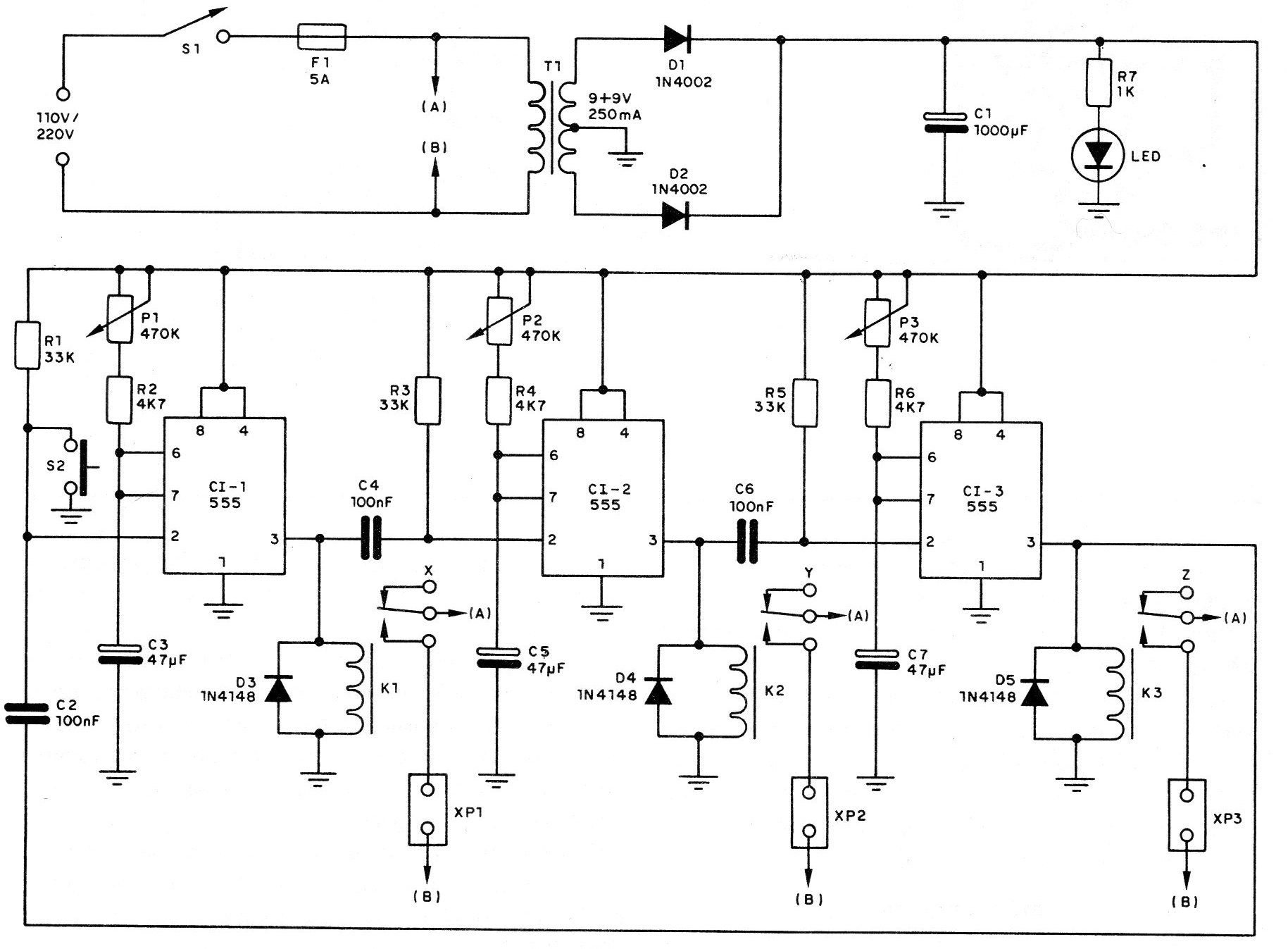
Our printed circuit board suggestion is shown in full size, for 3 stages, in Figure 4.
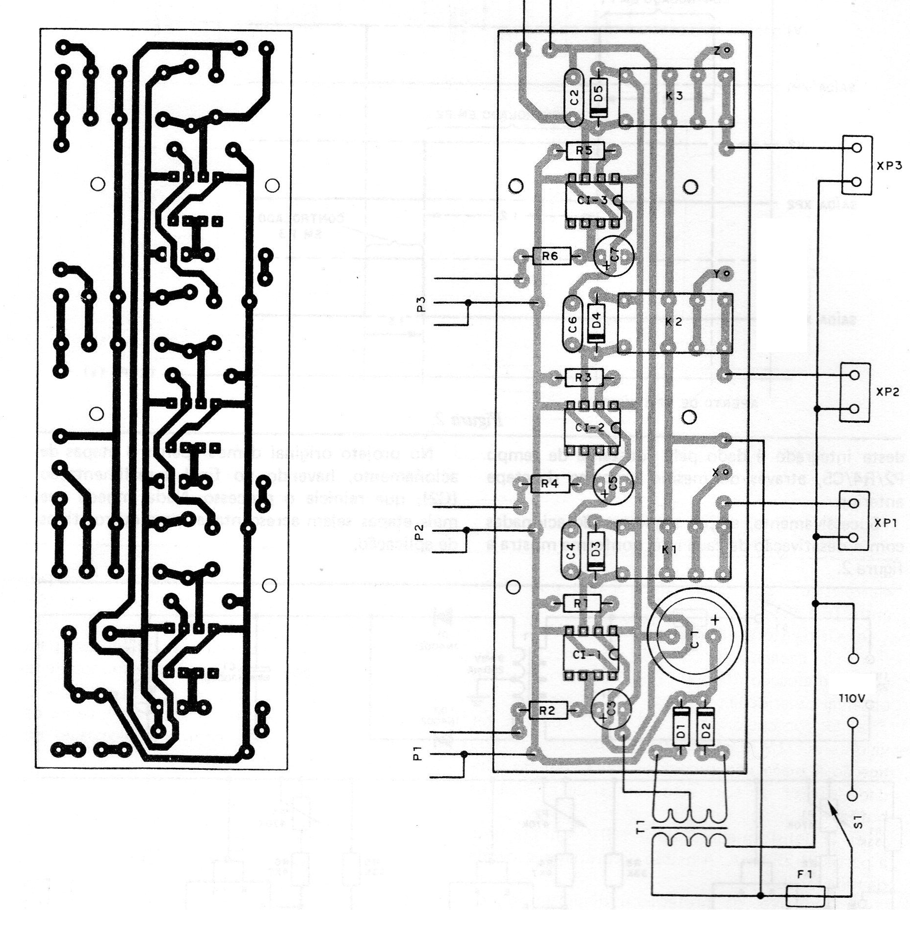
Both relays and integrated relays can be welded on the board. We only suggest that the reader, if using different integrated relays, try to have these components in hand before making the assembly, as it will be necessary to change the design of the board according to their pinning.
The main caution with the assembly is:
a) Observe the position of the integrated and the polarity of diodes which are commonly used as 1N4148 or equivalent.
b) Observe the polarity of the electrolytic capacitors. Their working voltage can be between 16 and 25 V.
c) The resistors are all 1/8 or ¼ W.
d) The capacitors C2, C4, C6 are ceramic with the marking 104 or .1 and it is not necessary to observe their polarity.
e) The potentiometers (P1 to P3) can have values ??up to 1 M for extended time periods. Their connection to the board does not need to be made with shielded wire. Cut their axes before putting the buttons.
f) The transformer is 9 + 9 V with current from 250 mA. The primary voltage depends on the local network.
g) The protection fuse is dimensioned according to the controlled loads. In the case, these loads should not exceed 4 A.
h) The relays may be the original (MC2RC2) or equivalent sensitive for 12 V voltage and contact current according to the controlled loads.
Finishing the assembly, the test is simple.
TEST AND USE
Connect common incandescent bulbs (5 to 100 W) into the XP1, XP2 and XP3 sockets.
Press S1 and then press S2. All potentiometers must be in the minimum time position.
The relays should be triggered in fast sequence powering the lamps. Act on each potentiometer to increase the lighting time of the corresponding lamp.
To use the appliance, only the desired time periods must be programmed into the potentiometers. Change the electrolytes if you want new ranges.
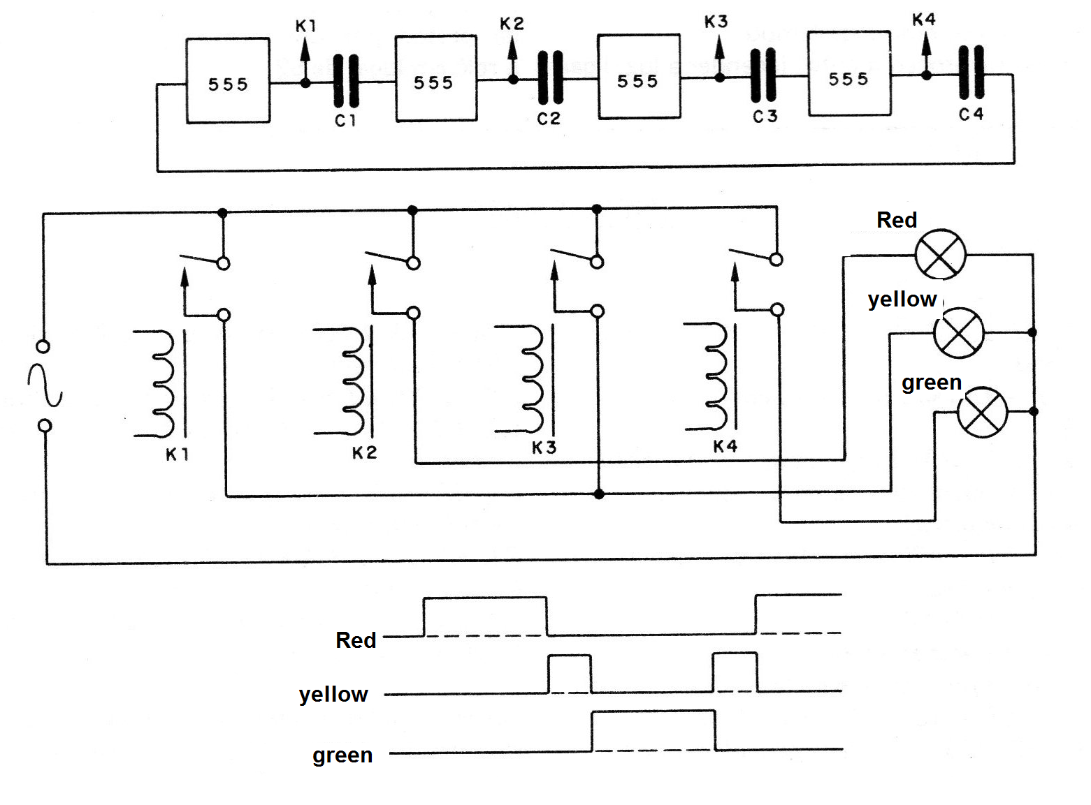
In Figure 5 we give a 4-step circuit for a traffic light, with the graph corresponding to its action.
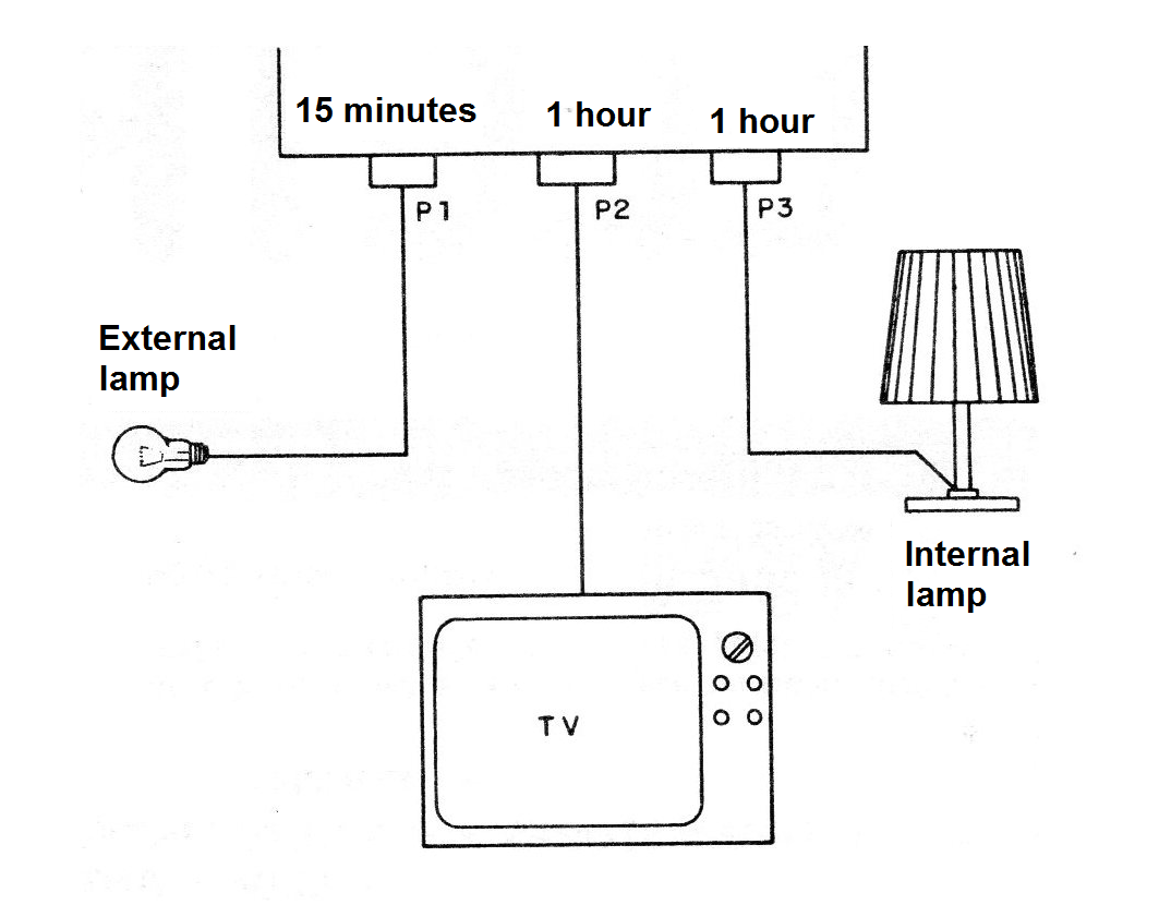
In Figure 6 we give a presence simulator circuit for residence, with intervals that in total can add up to 3 hours.
An important suggestion is to use an external device to start the operating cycle. It is enough, in this case, to replace S2 with a relay (contacts) which would be triggered by a sensor or even a time system.
A cycle of procedures (turning on the light, turning on the radio, etc.) could be initiated by a person walking through an optical sensor, which would trigger the relay instead of S2.
CI-1, CI-2, CI-3 - 555 - integrated circuits - timer
D1, D2 - 1N4002 or equivalent - silicon diodes
D3, D4, D5 - 1N4148 - general purpose diodes
LED - red LED, common (optional - not placed on the board)
P1, P2, P3 - 470 k or 1 M - linear, common potentiometers
F1 - 5 A fuse
S1 - single switch
S2 - pressure switch (start)
K1, K2, K3 - relays
XP1, XP2, XP3 - power sockets
T1 - transformer with a primary according to the local power grid and a secondary of 9 + 9 V with 250 mA or more
C1 - 1000 uF x 16 V - electrolytic capacitor
C2, C4, C6-100 nF (104) - ceramic capacitors
C3, C5, C7 - 47 uF x 16 V - electrolytic capacitors (see text)
R1, R3, R5 - 33k x 1/8 W - resistors (orange, orange, orange)
R2, R4, R6 - 4k7 x 1/8 W - resistors (yellow, violet, red)
Miscellaneous: a printed circuit board, assembly box, potentiometer button, power cable, wires, welding, etc.