In our article “H Bridges – How they Work" (MEC003E), we detail the operation of these circuits explaining how it works and giving a certain amount of practical circuits, but there are many more.
So, if the reader does not know very well these circuits and intends to use it in his/her next project involving an Arduino, PIC or microcontroller, we suggest that you first take a look at it.
Then come back to this article and making the best configuration choice for your design.
H Bridge Shield for a DC Motors Control
This circuit has been obtained from an American engine documentation. The circuit accepts equivalent transistors according to the power of the controlled motor. The motor voltage does not have to be the same as that which powers the control logic which makes it possible to use it with microcontrollers.
Shield Using an H-Bridge with a Manual PWM Control
This motor control Shield with an H bridge has an additional trigger circuit for PWM control. This control is manual in principle, made by a potentiometer, but a resistive sensor can be used, that will then determine the speed of the motor. In a robot that follows the light, for example, using as a sensor an LDR we can obtain the acceleration when the light source is located. The circuit should operate with 5 V, because with lower voltages for the IC the MOSFET trigger can be problematic. Any power MOSFET can be used.
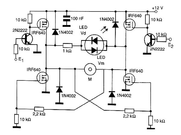
Full H-Bridge Shield with MOSFETs and a Direction Indicator
This full bridge has two additional LEDs which indicate the direction of rotation of the controlled motor. The bridge makes use of power MOSFETs and types must be chosen according to the current of the controlled motor. These transistors must be equipped with heat sinks. The bridge can be controlled by both 3 and 5 V signals and situation 11 is prohibited.
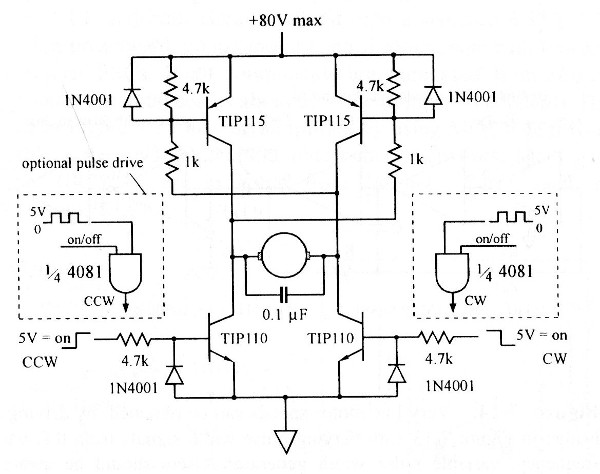
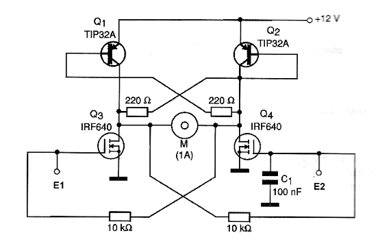
Bistable H-Bridge
This Shield switches the direction of rotation of a motor from pulses of 5V or more applied to the inputs E1 and E2, operating as an H-bridge power flip-flop. Transistors must be equipped with heat sinks. Depending on the MOSFETs used, it may be necessary to raise the amplitude of the pulses through an additional Shield (amplifier) to achieve efficient switching. The source for the motor must be separated.
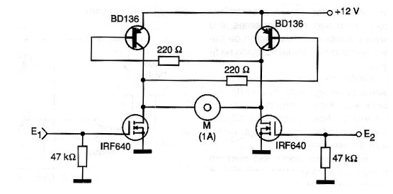
H-Bridge with a Power and Bipolar MOSFET
This mixed Shield can control engines up to 1 A and with the change of the BD136 even more. Transistors must be provided with heat radiators and the control must be done through the Arduino 5 V outputs, since MOSFETs may have difficulty switching with lower voltages. In some cases, it is even possible to use an Intermediate Trigger Shield to raise the voltage in the MOSFETs and thus obtain better switching.
Simple H-Bridge
The direction of rotation of the motor M can be controlled by an Arduino or other microcontroller via this bridge H. The levels 00 keep the motor stopped while 01 and 10 determine the rotation in two possible directions. Output 11 is forbidden because it causes the transistors to conduct at the same time, causing the circuit to short. The outputs can be modulated to obtain the PWM speed control in the desired direction.
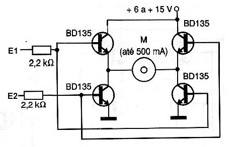
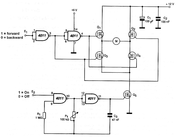
H-Bridge With Darlington
A bridge of greater sensitivity and therefore lower consumption for the outputs of the microcontroller is shown below, making use of Darlington transistors. This bridge has 4 possible states, 00 for the stationary motor, 01 and 10 for the two directions of rotation and the forbidden state 11 which leads all transistors to conduction and thus a short circuit situation. Transistors must be provided with heat sinks. Separate power for the motors can be between 3 and 15 V.
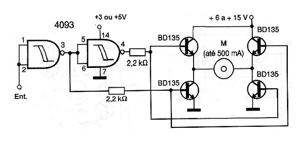
H-Bridge with Logic
This circuit has only two possible states 1 or 0 at the input, with the motor rotating in one direction or another. To stop or to start it, an additional command must be used, e.g. with a relay or transistor in series with the power supply. The supply of the integrated circuit must be done with the same voltage as the output used in the microcontroller. Transistors must be provided with heat sinks. Equivalent higher current transistors such as TIP31 can be used.
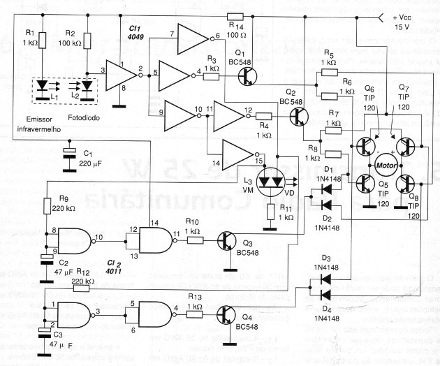
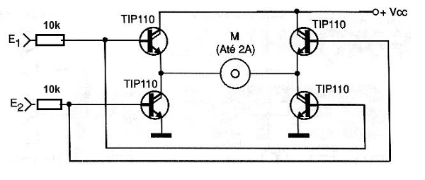
Digital Reverser For DC Motors
This circuit, which can also be adapted to function as a shield for microcontrollers, is from a 2003 documentation. The maximum current of the motor controlled depends on the transistors, and in this case is on the order of 1.5 A. Other Darlingtons of the TIP series can be used to control greater currents. The transistors of the H bridge must be mounted in heat sinks.