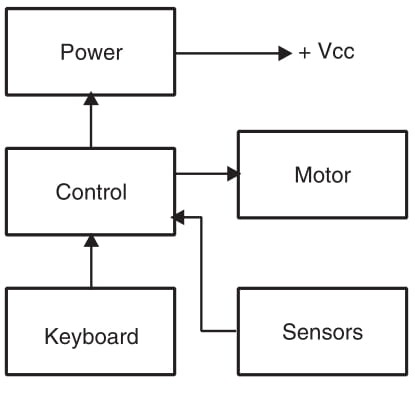
As mentioned, the number of blocks and their functions depend on the task the reader intends the machine to perform. When using the basic blocks, the designer must have in mind some important points.
Connectivity. The blocks must be designed so as to allow them to be interconnected without problems. This means that the signal sourced by the output of one block must be compatible with the input needs of other blocks. This book takes this fact into consideration, and most of the circuits can “talk” one with each other, as they have matched characteristics.
Compatibility. The designer of robotics and mechatronics projects must be attentive to the fact that the block he intends to use for a particular task must really have the ability to do it. A block that can control only 1 A across a load cannot be used to control a 2 A load. The designer must be sure that the block used to control a gripper can draw the necessary current to drive it.
Power drain. If the project is powered from a battery or cell, it is important to determine whether the battery can really provide enough current for all the blocks. Motors, actuators, and other transducers are the responsible for most of the energy drain in mechatronics and robotics projects.
The main problem occurs when all the transducers and actuators are activated at the same time. The high current drain can cause a large enough voltage drop to affect the operation of the entire system. It is a good idea is to use independent power sources for high current loads (such as motors, grippers, and actuators) and the electronic circuits.
If the circuit is powered from the ac power line, the same precautions are valid: use a large enough power supply to support all the devices that must be powered. It is also a good idea to use one power supply for motors, actuators, and other heavy duty loads, and another to power the electronic circuits.
Suggested Projects
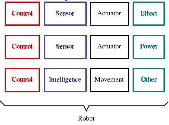
At this point, the reader should be ready to conceive a first project in mechatronics or robotics and commit the idea to paper. The functions your machine will have, and what you intend it to do, can be laid out using basic blocks such as the ones we have already discussed. Using the basic blocks shown by Figure 1 you can design a functioning machine.
Automatic Arm
This simple mechatronic project consists of a robot arm or mechanism that can pick up objects from one place and put them in a basket or another location, as suggested by Figure 2. The basic configuration in blocks is shown in the same figure and includes the following functions:
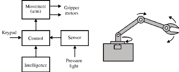
Control. Obtaining information from a keypad or a joystick.
Actuator. Moving the arm and the gripper. An alternative for the gripper in a simplified project is the use of an electromagnet, if the objects to be moved can be attracted by it.
Sensor. Optionally, we can send information to the operator such as whether the basket is empty or full, whether there are obstacles, and if the object falls before it is placed in the basket.
Power supply.
Effects. Light or sound effects can be added; a light can flash or a counter can be ratcheted up when the object falls into the basket.

Walking Robot
This is certainly the most attractive among all the projects the designer of robotics and mechatronics projects can adopt. Figure 4 show the basic blocks to form this kind of robot. Its functions are as follows:
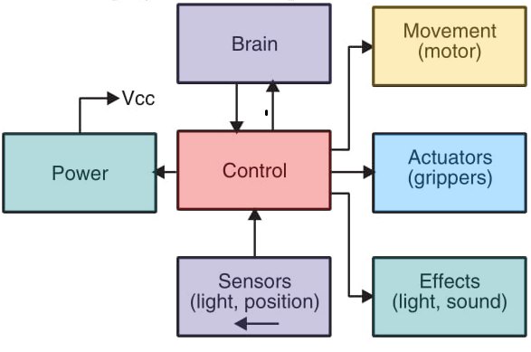
Control. The signals for this block can be sent by the operator (via radio control, IR link, or a cable), or they can be generated by sensors engaged by the moving system (motor, wheels, tracks, or legs). If the robot has other movable parts (e.g., arms or a head), they can be controlled by this block.
Brain. Some intelligence can be added with the aid of sensors. The robot can make some decisions independently from the operator if we use a logic block for this task.
Sensors. The sensors can inform the operator about the presence of obstacles and instruct the brain to make required decisions.
Actuators. This robot can be equipped with a grip or other actuator to move objects. An “artificial hand” can be adapted from toys such as the one shown in Figure 5.
Effects. Light and sound effects can be added to this robot. A solid state audio recorder can be used to make it speak some words or send some kind of warning message while walking around. The effects are very important if the robot is to be demonstrated at fairs, public exhibitions, or school contests.
Power. This kind of robot is powered from batteries.
Robot—Follow the Line
An interesting and classic project is the “follow-the-line” robot. It is equipped with LDRs or phototransistors as sensors in a differential “intelligent” configuration as shown by Figure 5.
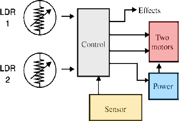
The light sensors are excited by the light reflected by a white line drawn in the ground such that the control circuit of the robot can direct it to follow the line, as suggested by Figure 6.
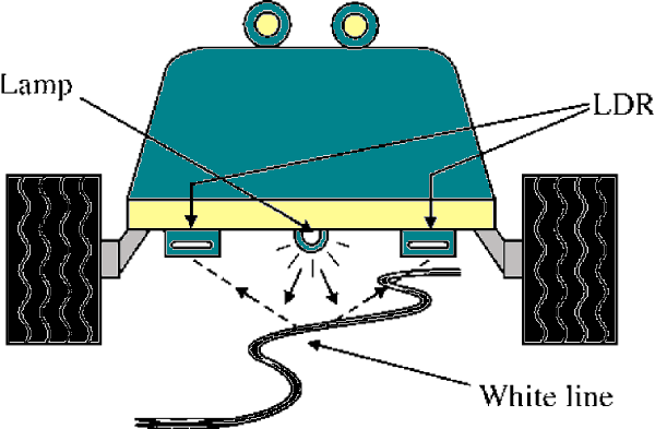
In the basic version, the line forms a closed loop, but the designer can add some other sensory blocks to make it seek out the line and then follow it when found.
The basic blocks for this robot are:
Sensor. You can use LDRs or phototransistors.
Control. This block is operated directly from signals from the sensor or the intelligence block.
Intelligence. This block is formed by a neural comparator that senses and compares the light picked up by the sensors.
Power. A battery is the best solution but, for experimental purposes in a lightweight prototype common cells are suitable.

Effects. Light and sound effects can be added if the reader deems them to be important.
Automatic Elevator
The automatic elevator is another classic project in mechatronics and automation. As Figure 8 shows, it is formed by creating a model of a building with an elevator. The number of floors can be as many as ten in a typical project.
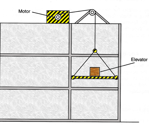
The aim of the project is automatic operation using sensors at every floor. A keyboard is used to call the elevator to a specific floor, and an intelligence block can be added if we want it to make special decisions. This block can make the elevator “decide” which floor to service first if two calls are made at the same time. The decision depends on the floor at which it is located at that moment. The automatic elevator can be designed using the blocks shown in Figure 9.
