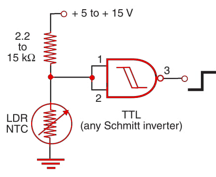
The output of the block shown in Figure 1 is low when the sensor, if an LDR, is in the dark. When the sensor is illuminated, the output of the circuit passes to the high logic level. The circuit has the snap action needed to drive logic blocks, since a Schmitt inverter is used.

For CMOS applications, a logic inverter can be made using one of the four gates of a 4093, and for TTL applications the 7402 can be used. The same characteristics described in the previous articles in are found in this circuit.


