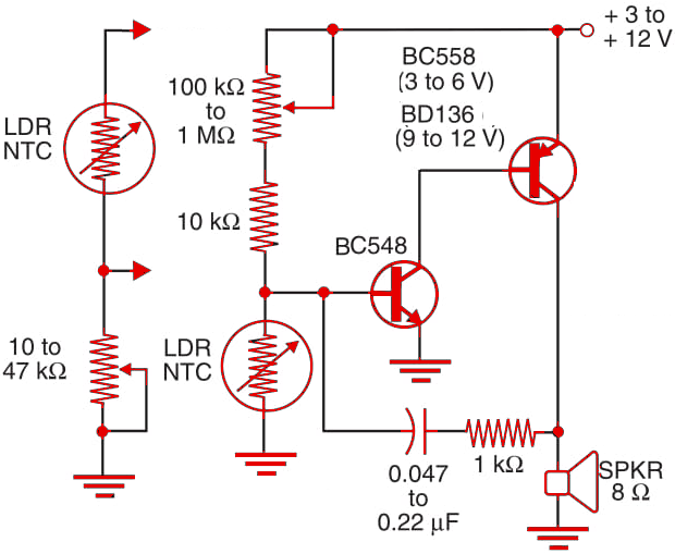
The circuit of Figure 1 is an analog-to-digital converter (ADC or A/D converter) the amount of light falling onto a sensor, or the temperature of a sensor, is converted into an oscillation frequency. The sensor’s resistance and capacitor C1 determine the output frequency range. With the values shown in the figure, the circuit produces an audible tone that is emitted by a loudspeaker.

Applications for this circuit in robotics and mechatronics include an audible reaction from a robot when it touches hot objects or when it “sees” a flash of light. By adding potentiometer P1, is possible to put the oscillator on the threshold of oscillation so that it is triggered by light falling onto the sensor or when the temperature rises above a certain value.
P1 and the sensor can be interchanged to invert the action of the circuit (i.e., it is triggered with by darkness or when the temperature falls). This circuit also operates with other resistive devices such as touch sensors and pressure sensors.


