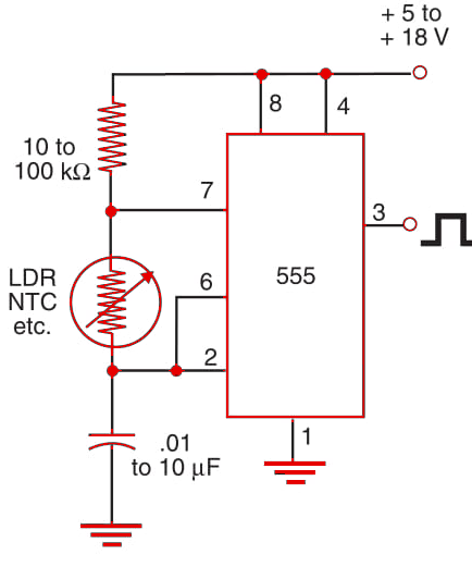
This circuit can also be used with touch or pressure sensors. The circuit shown in Figure 1 produces a squarewave signal in the range from a fraction of a hertz to 500 kHz, depending on R and C in the circuit. Frequency is calculated using the formula in the diagram. By replacing one of the branches of potentiometer P1 in the circuit shown in Block 92, it is possible to have a temperature/light-controlled pulse width modulation (PWM) circuit.


