
What are stepper motors?
Stepper motors, like ordinary motors, can be said to be devices which convert electrical energy into available mechanical energy in the form of torque. However, stepper motors have some characteristics of their own that differentiate them from ordinary motors, namely:
a) Stepping motors act as positioning devices as they can stop in a perfectly controlled position.
b) Stepping motors may also function as perfectly controlled speed motors, being energized in a particular order.
These features are added to others which make them ideal for computer, industrial and control electronics, robotics and mechatronics applications:
a) They may have their shaft positioned at an angle proportional to the number of input pulses.
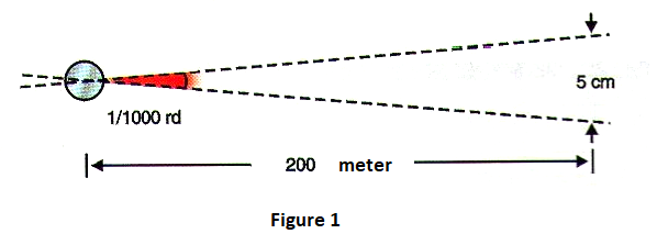
b) The errors which occur in the positioning of its shaft are very small and are not cumulative. A stepper motor can be positioned with an accuracy of 1 thousandth of radian typically, as Figure 1 suggests.
c) The open loop control is possible due to the use of digital signals for this purpose.
d) Starting, stopping and reversing responses are very fast.
All of this makes the stepper motor a unique element in many applications.
Typical Applications:
In Figure 2, we have an industrial application of a stepper motor consisting of a liquid pump with constant flow.
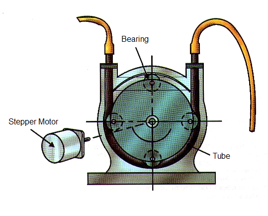
The stepper motor is controlled by a processor circuit which receives information about the flow of liquid keeping it constant.
In Figure 3, we show the application of the stepper motor in the positioning of the reproducing and recording head of a floppy disk drive.
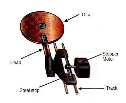
Figure 3 - Floppy Disk Stepper Motor
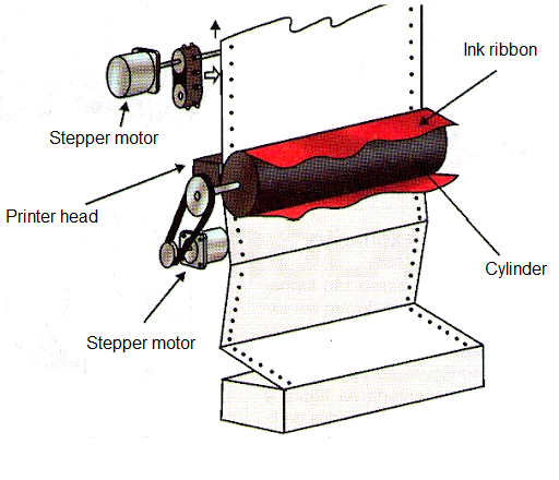
Another important application is illustrated in Figure 4, where the stepper motor is used to both position paper forward and backward as well as to precisely move the print head over the paper.
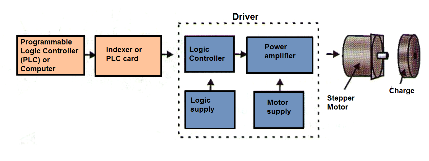
In automation, elevators, robotics and mechatronics the stepper motor can be employed in precise motion controls with the block structure shown in Figure 5.
STEPPER MOTOR TYPES
There are three basic types of stepper motors, which are:
* Variable reluctance
* Permanent magnet
* Hybrid
Let's analyze the main characteristics of each one.
a) Variable reluctance:
In Figure 6, we have a sectional view of the construction of a variable reluctance stepper motor.
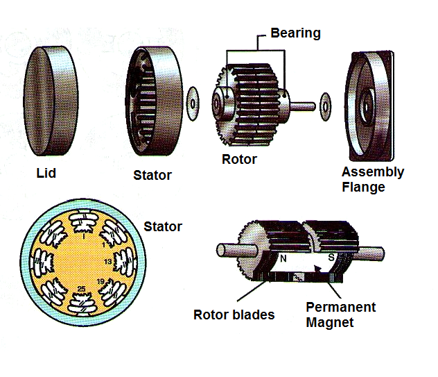
As we can see, it is the action of coils creating fields which positions the teeth of ferromagnetic material coupled to a moving shaft. The multipole rotor of this motor is made of soft iron, while the stator is multilaminated.
The rotor of this type has a small inertia.
b) Permanent magnet:
In Figure 7, we have a sectional view of such an engine.
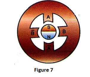
This motor rotates when the magnetic field of energized coils interacts with a set of permanent magnets. The rotor is radially energized.
This type of motor is suitable for applications where precision is not required, and the cost is important as it has a low price. Another feature is its operation with large step angles, between 45 and 90 degrees.
c) Hybrids
These motors have the construction of the type illustrated in Figure 8.
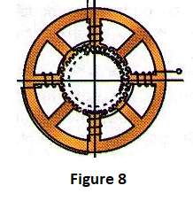
The rotor is axially energized. Both rotor and stator are multipolar.
The main advantage of this engine is its accuracy with steps of 1.8 degrees in the most common types, and even reaching 0.36 degrees in the most accurate types.
Driving Modes:
Stepper motors are formed by 4 coils which must be driven in a certain order, or according to the desired positioning. The typical configuration of these coils is shown in Figure 9 where we also see the most common modes of connection, which are unipolar and bipolar.
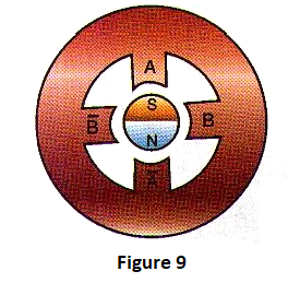
The phase driving of these coils is application dependent and can be done in the following ways:
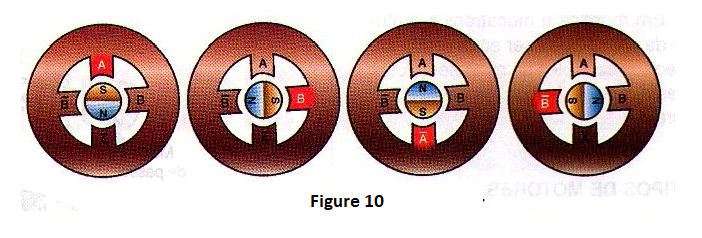
**A phase or wave
In this driving each coil is energized separately in sequence according to the rotor positioning movement, as shown in Figure 10.
Two phases
In this mode of operation, exemplified in Figure 11, the coils are energized two by two so that the rotor can stop at intermediate positions given by the resulting forces of attraction between the coils.

One-Two Phases
In this operating mode, one and two phases are alternately driven leading the rotor to the desired movement or position, see Figure 12.

Two phases or microstep
In this mode we have the application of different voltage levels in the coil, which allows the positioning of the rotor at points intermediate to the poles of the energized coils, see Figure 13.
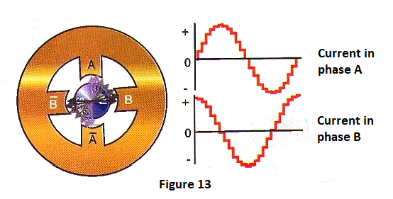
Scaling the stresses applied to the coils will determine how many intermediate points between two steps (90 degrees) can be obtained.
Conclusion:
The choice of type and mode of operation depends on the application.
Thus, to know how to use a stepper motor correctly there are other important information that will be addressed in the course of new articles.


