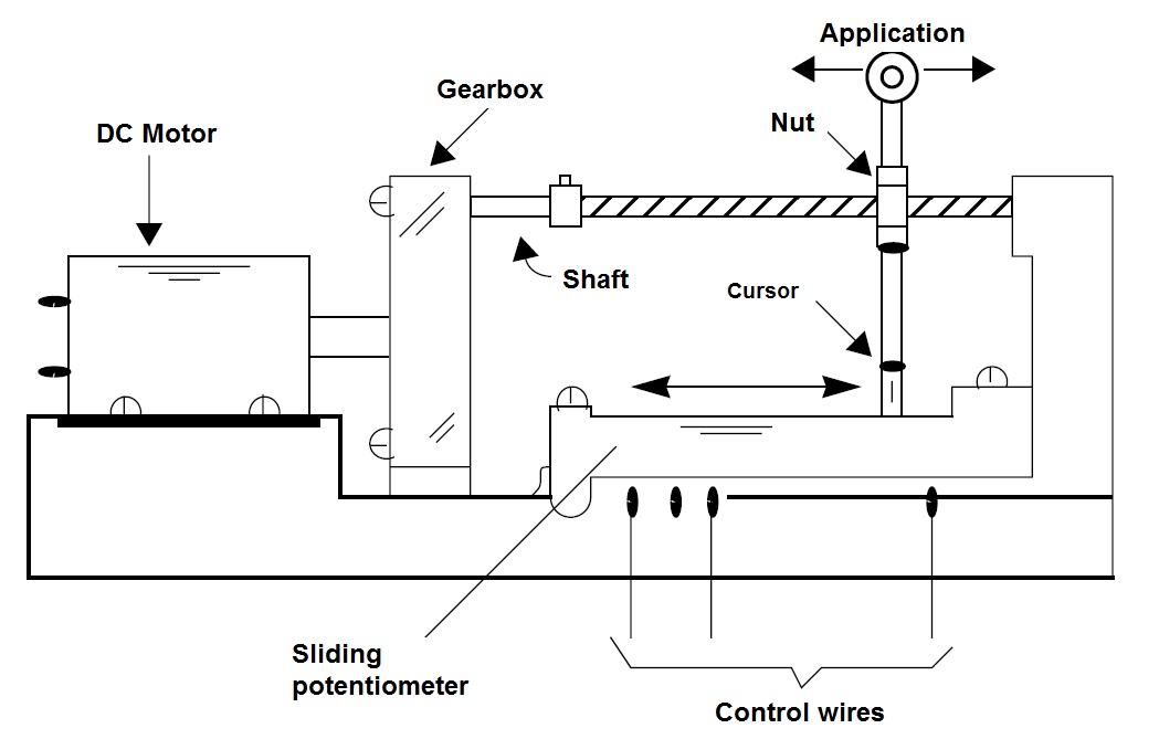
An interesting didactic work is the construction of an experimental servo with common components such as gears, screws, a gearbox and a direct current motor. Figure 1 shows how you can do this.
This servo is voltage controlled but can be adapted to operate on pulses or other signal types. The operational amplifier can be replaced with an equivalent. The output transistors support a current of 500 mA, but if the motor used is larger, up to about 2 amps, the pair can be replaced by a TIP31 and a TIP32.
These transistors should be built on appropriate heat sinks, given the heat generated in the operation. The circuit is shown in Figure 2.
A gearbox is adapted to rotate an "endless screw" which moves a nut. The nut is attached to the cursor of a sliding potentiometer which provides feedback to the circuit.
When a voltage is applied to the circuit input (signal), the motor moves until the potentiometer reaches the position where the feedback voltage equals the input voltage.
At this point, the operational turned on as a comparator clears its output and the engine stops. If the input voltage is changed, the motor will start, changing the cursor position until the input voltages match once more.
In practical realization, the gearbox is a critical element as it cannot be too fast and there should be an appropriate time for the system to respond to the feedback. The movable axle can be used to move levers, for example the helm of a boat, or a gate in a mockup.
This is an excellent design to be demonstrated in schools (STEM), controlling for example, a gate.


