

If you have dreamed of creating a combat robot that can destroy or knock out the enemies, rivals, space invaders, or other supernatural creatures, you must take a look at this project.
RobCom is the answer for your aspirations-your dream coming into reality.
Using inexpensive and common parts, even inexperienced readers who may not yet be prepared to build complex circuits with microprocessors can build the RobCom.
The reader will be able to build the RobCom and challenge his or her friends to a real combat of robots.
You can also invite your colleagues to build combat robots. Ask them to put into the project all their imagination, to create weapons, and to build defenses so they won’t be knocked out in the first encounter.
RobCom was one of the projects proposed by the author to his pupils of the mechatronics course at Colégio Mater Amabilis in Guarulhos, Brazil. Figure 1 shows some of the projects made by the students.

You can see how these student constructed their destruction machines.
The RobCom
RobCom is a remote-controlled robot built with common parts. In the basic version, it is built to carry a rubber balloon that it is protecting and three needles as weapons.
The reader can add other weapons, of course, depending on the rules of combat agreed upon by the other competitors.
To make the project easier, the remote control uses a cable. Some advantages exist to using a cable in place of other remote control means, such as infrared (IR) or radio frequency (RF). Even a microcontroller with WiFi such as the Arduino, PIC or MSP430 can be used.
Beyond the simplicity of the cable method (no special circuits are required), the problems of interferences and noise, common in the places where the combat takes place, don’t, exist.
RobCom has two small DC motors directly driving two rear wheels, which are made of standard CDs.
The single front wheel is able to turn freely in any direction. The recommended front wheel is one that can be found in old office chairs or other furniture.
Figure 2 shows the wheel used in the robot.

The control unit, which is placed at the end of a cable, is simply a. small box with two special switches and a joystick.
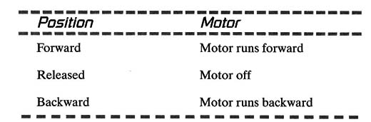
The switches can control two circuits (two poles) at the same time, and each switch has three positions. When the joystick is in the central position, the controlled circuit is disabled; no power is released to the motors.
Certain positions of the switches control certain functions of the motor, as shown here:
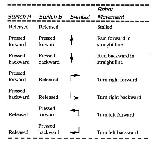
Combining the three positions of the switches, the robot can run in any direction, as the following table shows. The arrows indicate the direction of movement.
RobCom is powered by four AA cells placed in the control unit. This placement reduces the weight of the mobile unit, increases the mobility, and is very important in combat.
Objectives – The Combat
The basic idea of robot combat is to put two RobComs in an arena formed by four pieces of wood, as shown in Figure 3, and let them try to pop the other’s balloon using needles as weapons.

Controlling the forward and backward movement of the robot, the player can find the best position for an attack without exposing his or her own balloon to the attack of the enemy. Strategies must be created by the RobCom evil genius to win the combat.
The winner is the first robot to pop the enemy’s balloon. The balloons can have a tiny amount of flour or talc injected in them, adding a realistic effect for the explosion. A cloud of smoke will then announce that the balloon is popped and the combat is over.
A normal combat session usually lasts from 1 to 5 minutes. In an organized competition, a simple elimination process can be used.
Rules are very important in order to avoid major differences among the competitors and to level the playing field. Rules include specifications for maximum dimensions of the robots, the size of the rubber balloon, the use of defense screens, the length of the needles, the types of motors used, the power supply voltage, and so on.
Rules for the actual combat are necessary, too. At the end of this project is a list of rules that we have found are useful in our combat.

The Project
The RobCom is a robot that runs on three wheels.
The front two are used to turn the robot in the desired direction, and the third is a free wheel.
Two small DC motors are coupled directly to the wheels, which are made with CDs or some other material of the reader’s choice.
If the reader wants, he can use a assembled mechanical structure as the one recommended for Arduino, PIC and other microcontrollers as the one sohwon by figure 5.

The motors are controlled by a remote control, wired to the robot by a 3-meter cable.
As indicated previously, the use of a cable makes the project easy to build and very inexpensive, as no special materials are needed. The remote control also houses the cells that power the motors.
Two switches allow the robot to move backward and forward and to change direction.
The chassis can be made using common materials such as cardboard, CD boxes, plastic, wood, and so on. It is up to the reader to use his or her imagination to create his or her own version while following the rules of the competition.
When creating your RobCom, it is important to reduce the weight, making it as fast and well balanced as possible.
How to Build
The basic RobCom is the one described in the introduction. Of course, the evil genius can change the RobCom by adding new weapons or defenses according to the combat rules.
The Electric Circuit
Begin your project by building the electric circuit. The simple schematic diagram for the RobCom is shown in Figure 6.

As we can see in the figure, the single power supply is formed by four AA cells. This supply powers two small, 6-volt DC motors via S1 and S2.
S1 and S2 are a special arrangement of two switches with three positions each. In the middle position, the switches are off.
S1 and S2 determine the direction of the motors.
The switches send the power to the motors by a special four-wire cable. The recommended length of the 4 X 26 American wire gauge (AWG) cable is 3 meters.
The switches are placed in a small box (plastic or other material) forming the joystick. The different colors of the cable wires are important and will help the reader know where each must be soldered.
Figure 7 shows the electric circuit assembled.

S1, S2 - 2 poles X 3 through switches (see text)
B1 - 6 volts of power (4 AA cells with holder)
M1, M2 - 6-Volt DC motors
3 meters of four wire cable (4 x 26 AWG)
Plastic box
Figure 8 shows the basic mounting of the robot, detailing how the motor is coupled to the wheel.

Figure 9 shows a rear View of the robot.

The motors are glued to the Cdbox They are kept in contact with the CD by the force of a rubber band. This makes it possible to transmit all the power to the robot.
Putting the Pieces Together
The next figures show the sequence of operations to mount the robot.
Figure 10 shows the free wheel fixed to the CD box used as a chassis and how to insert a metal sheet between them to keep the structure rigid.

Figure 11 shows how to add an isolation sheet to the CDs to increase the adherence.

Rubber bands glued to the CD can also be used to accomplish this. The reader is free to create the best way to increase the adherence, making the robot faster and agile.
The plastic wheel, taken from a toy, is glued to the CD. Small plastic cars and other toys are good sources for this wheel. I prefer the type with metallic axles. Figure 12 shows how to glue the wheel.

Pieces of cardboard can be used to make supports for the wheels. The spindles of the wheels are inserted into the drinking straws. At the end of the spindle, a small piece of a plastic cover connects the spindle to the cardboard support, as shown in Figure 13.

This cover can be a small piece of the tube from a ballpoint pen or even the casing from an elec- tric wire.
The motors are glued to the box. Be sure that the motors’ shafts will be aligned with the wheels (the CDs).
Figure 14 shows the motors glued and con- tacting the CDs. The motors are forced to maintain contact with the CDs by a rubber band holding them in place.

To increase the transmission power of the motor to the CD, the spindle is covered with a small glove.
As mentioned previously, the glove can be made using a piece of plastic tube taken from a ballpoint pen or even a plastic cover from an electric wire.
The arms of the robot are made with needles, placed in a piece of cardboard as shown in Figure 15.

Figure 16 shows the RobCom ready for combat.

Finally, you can attach the rubber balloon to the robot using a rubber band.
Testing and Using
Insert the batteries in the cell holder. Pressing the switches in the control unit, the motors should be activated. If not, check the solder and the cable. If one or both motors run in the opposite directions (e.g., forward when you press backward), invert the wire of the motor.
With the robot on the ground, test to see if the robot will move freely in all directions when you press the controls. If the motors have difficulties in moving the robot, verify that they are pressing against the CDs with the necessary force.
If all the movements are satisfactory, your RobCom is ready for combat.
The Combat
The reader is certainly free to create his or her own rules for competition. However, we can offer some suggestions based on the experience of many combat sessions organized in the school where the author teaches.
Figure 17 shows several RobComs in an arena, waiting for the beginning of the contest.

Combat Rules and Specifications for the Robot
To avoid major differences among the robots, it is important to establish some rules regarding the robot and the competition. The robot characteristics should be as follows:
The length of the robot must be between 15 and 25 centimeters.
The maximum number of needles used as arms should be three.
The maximum length of the needles should be 20 centimeters (including the support).
The screen in front of the robot should be lim ited to 10 X 15 centimeters.
All the robots should use the same type of motor.
The power supply must be four AA cells for all robots.
The rubber balloons must be equal in size.
No other weapon is allowed (or otherwise combined).
The arena is formed by four pieces of wood with the dimensions between 3 X 3 and 4 X 4 meters.
Combat Rules
The competitors cannot enter the arena.
The competitors cannot pull the robots by the remote-control cable.
The competitors must begin at opposite corners of the arena.
The combat begins when the referee gives the order.
The combat ends when the balloon of one competitor is popped.
If the two balloons are exploded at the same time, the robots must compete against each other in a second round to determine the winner.


