Many changes can be made to the original project specifications of the RobCom. The following are simple examples of the changes that can be made:
Wood rods can be used to substitute for the plastic chassis.
A plastic chassis with different formats can be used.
The same project can also be used with vehicles other than combat robots. The reader can mount his or her own walking robot using the control system described here. The next figure shows such a robot.

Cross Themes
The control of movement is a theme that translates easily into the physics curriculum. Teachers who want to explore this as a cross theme can invite the pupils to research the next items:
Analysis of movement: Describe the type of movement the robot makes during combat and how fast changes in direction or speed can alter the equilibrium.
Friction: Analyze the effect of friction in the robot mobility.
Transmission: Find the best way to transmit the power from the motor to the wheels. Think about the use of gears.
Circuits and Ideas
The basic circuit used in the project is very simple. It uses no electronic pieces and no complex elements.
The reader who is experienced in electronics can upgrade the circuit and create some interesting projects.
a) Using a Joystick
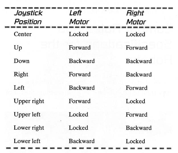
The figure below shows how a common joystick, such as the ones found in Video games or PCs, can be used to control the two motors in the RobCom.

The circuit uses four relays to control the two motors. The four switches of the joystick are used to power the motors on and off or to reverse the current across them. The position of the joystick affects what happens to the motor:
Using a Joystick
D1 to D8 - 1N914 or equivalent silicon diodes
K1 to K4 - 6 V to 12 X 50 mA reversible relays (select voltage according the motor)
Using a Pulse Width Modulation (PWM) Control
A PWM control for the motor will allow the reader to change the speed of the RobCom. The PWM control is described in detail in Project MEC025E.
Figure below shows how to add a PWM block to the RobCom. Notice that only one PWM control is necessary to change the speed of both motors. Or if the reader wants, he or she can use one PWM control for each motor.

The PWM blocks can be controlled by a microprocessor such as the Arduino, PIC or MSP430.
Adding Weapons
The reader can put his or her imagination to work creating new weapons for the RobCom. Of course, it is important to be sure the weapons meet combat rules.
Next figure shows how a small DC motor can be used to add movement to the needle, making it much, more dangerous as a tool against the enemy.

Another idea is to couple a rotary ball with nee- dles, as shown in the next figure. In this case, the reader must take care that the ball does not pop his or her own balloon.

Adding a Death Circuit
An interesting improvement for the project is a death circuit. This circuit is formed with two reed switches and a magnet, placed as shown in figure below.

As we can see, the current flows across the motors and passes through the reed switches. The magnet is attached with a rubber band inside the balloon. If the balloon is full, the magnet touches the reed switches, and the motors are powered.
If the balloon pops, the magnet falls and the reed switches open. The motors are no longer powered, and the robot stalls.
Sound Circuit
Figure below shows a simple sound-effect circuit for the RobCom.

If a 47 nF capacitor is used, the circuit generates sounds like a siren produces when the motors are activated. If a 10 µF capacitor is used, the circuit generates pulses imitating a machine gun.
SPKR is a small 8 ohm 2.5 to 5 cm loudspeaker P1 adjusts the sound.
H-Bridge Control
The digital control of the RobCom can be implemented by using an H-bridge.
This idea is based on the fact that four transistors can be used to control the current across a motor in the same way a doublepull/double-throw (DPDT) switch controls the current.
The same circuit can be controlled by a microcontroller such as the Arduino, MSP430 or PIC. In this case the IC (4011) must be powered froma 5 V supply.
The transistors in the bridge can be powered from other voltages sources, in the range from 5 to 24 V accordingmotor.
The circuit proposed in the next Figure is a full bridge or H-bridge using four Darlington transistors.

This bridge can be used to control up to 500 mA motors. Other transistor of the TIP series can be used for higher currents.
Using an H-bridge for the control has two advantages. First, the current across the cable is reduced.
Second, logic signals can be used in the control. In this case, besides the microcontrollers also a computer can be used to control the RobCom.
The circuit works as follows: When the forward (FW R) input is high, Q1 and Q4 are on and the current flows across the motor in the direction indicated by arrow 1. When the rewind (REW) input is high, Q2 and Q3 are on and the current flows as indicated by arrow 2.
Notice that Q1 and Q3 can’t be turned on at the same time, as can Q2 and Q4, because that would mean a short circuit for the current between + Vcc volts and ground. It is a forbidden state that can cause the transistor to burn.
The circuit can be controlled in the following ways:
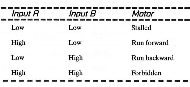
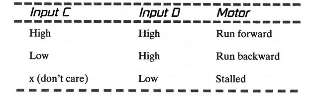
Figure below shows how to add a fifth transistor and a logic system to avoid this forbidden state.

Two outputs of a microcontroller can be used wih cthis circuit. Controlling the direction and the other giving the speed with a PWM program.
In this case we can consider the circuit a Shield for microcontrollers.
The bridge works in the following manner:
This same bridge can be implemented using the same bipolar transistors used in the BD135 (500 mA) or TIP31 (2 A), as shown in the next Figure.

Using an H-Bridge
IC1 4011- 4 NAND gates (CMOS integrated circuits [ICSD
Q1 to Q4 TIP122 negative-positive-negative (NPN) Darlington transistors
R1 to R5 - 10 k ohm x 1/8-watt resistor (brown, black, orange)
M - DC motor (up to 500 mA)
Using Gearboxes
The mechanics of the RobCom can also be improved with the use of gearboxes. As shown in Figure 7, the RobCom can be powered by small gearboxes, increasing the efficiency and allowing the robot to be built in a more compact manner.
The gearbox can be used to power the CD wheels or plastic wheels.

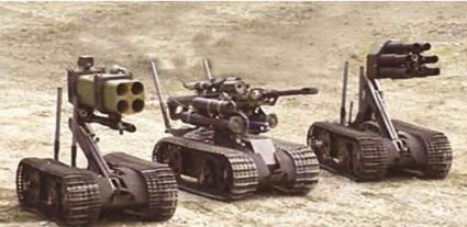
Technologg Today
Combat robots are real these days. Military robots can be used to fight, to carry resources, on rescue missions, or to go where it is too dangerous for a human soldier.