

Description: This package contains two 4-Channel Mux/Demux with two binary control lines and an inhibit input. The input signals may be used to select one of the 4 pairs of channels to be turned DN and connected from the differential analog inputs to the differential outputs.
->Functional Diagram and/or Package:
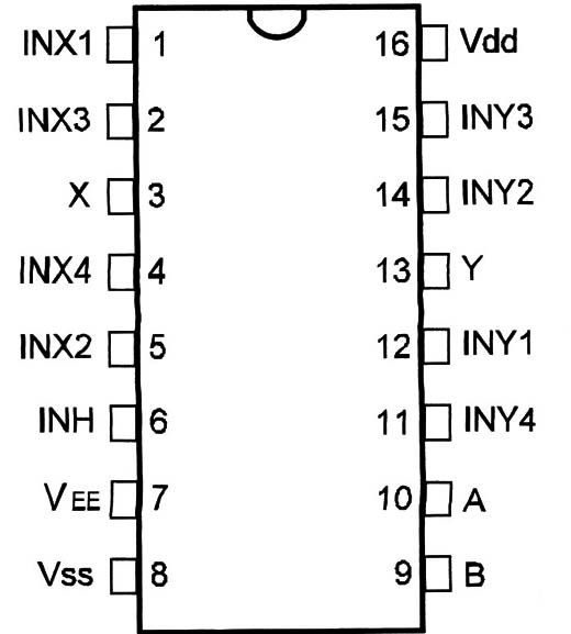
Pin Names:
Vdd - Positive Supply Voltage [BV to 'ISV]
Vss - Ground
INX1, INX2, INX3, INX4, lNY1, INY2, INY3, INY4 - lnputs/Dutputs
X, Y - Outputs/lnputs
INH - lnhibit
Vee - -5V
A, B - Control Inputs
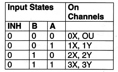
Truth Table:
Operation Mode:
a) Analog Mode
- -5V is sourced to pin 7 - Pin 'IB is connected to a +5V source and pin 8 to ground.
- The control inputs [A, B) determine the selected channel according to the truth table.
-I NH must be “0”.
- If INH = 1, no channel is selected.
b) Digital Mode
- Pin 7 and 8 are grounded and Vdd between 8 and 'ISV is sourced to pin 16.
- The selected channel is determined by the logic level applied to the control - lines A and B. INH is “0”.
- If INH = 1 no channel is selected.
- In the OFF state the device is an open circuit, and When ON, represents a very LOW resistor [see Electrical Characteristics].
Electrical Characteristics:

Other Devices:
The 4051 is a 1-of-8 switch and the 4053 is a triple 1-of-2 switch.
Applications:
Analog and Digital Multiplexing and Demultiplexing
A/D and D/A Converters
Signal Gating
Observations:
The minimum load resistance is 100 ohm.
The maximum controlled current is 25 mA.
The maximum amplitude of analog sinals is 10 Vpp.


