

Description: This package contains 3 differential 2-channel analog Mux/Demux. This device has three separated control inputs and an inhibit input. Each control input selects one of a pair of channels that are connected in a single pole-double through configuration.
Functional Diagram or/and Package:
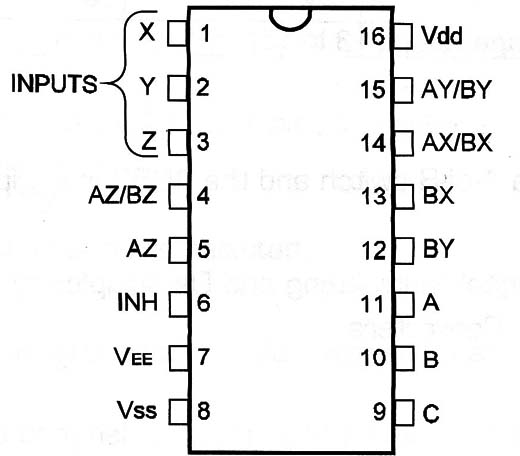
Pin Names:
Vdd - Positive Supply Voltage [BV to 15V]
Vss - Ground
AX, BX, AY, BY, AZ, BZ - Inputs/ºutputs
X, Y, Z - Outputs/lnputs
lNH - lnhibit
Vee - -5V
A, B, C - Control Inputs
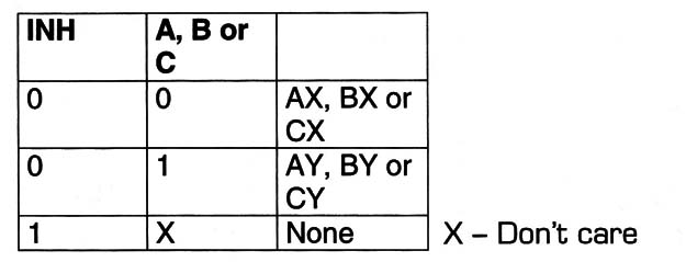
Truth Table:
Operation Mode:
a) Analog Mode
- Apply -5V to pin 7 and ground pin 8. Pin 8 is sourced with +5V.
- The selected channel is determined by the logic levels in the control lines A, B, and C. INH must be “0”.
- A controls the first switch. If A is high, AX is connected to X. if A is low, AY is connected to X. See truth table for more details.
- If lNH =1 all the switches are OFF and no channel is selected.
b) Digital Mode
- Ground pin 7 and pin 8. Pin ”IB is sourced with voltages between 3V and 15V.
- The selected channel of each switch is determined by the logic levels applied to the control lines A, B, and C. INH must be “0”.
- lf INH = 1, no channel is selected.
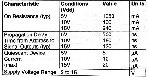
- In the ON state the devices acts as a low value resistor [see Electrical Characteristics].
Electrical Characteristics:
Other Devices:
The 4051 is a 1-of-8 switch and the 4052 is a dual 1-of-4 switch. Each has the same electrical characteristics and operation mode.
Applications:
Analog and Digital Multiplexing and Demultiplexing
Signal Gating
A/D and D/A Converters
Observations:
Maximum amplitude of the analog signal must be limited to '10Vpp
The minimum load resistance is 100 ohm.
The maximum current through the device is 25 mA.


