Note: this article was originally published in Portuguese in a Brazilian magazine and after include in a book of the author.
TTL to CMOS (5 V)
The first case is shown in Figure 1.
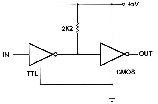
A TTL block drives a CMOS block and both are powered from a 5V supply.
The 2k2 resistor is used to pull up the output of the TTL gate because the very high input impedance of the CMOS blocks acts as an open circuit.
TTL to CMOS (Different Voltages)
If the CMDS circuit is powered from a voltage higher than 5V, the circuit shown in Figure 2 is the recommended for use.
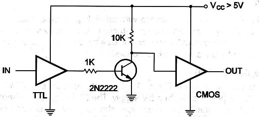
The transistor is wired in the common emitter configuration and acts as a “buffer-inverter” for the signals coming from the TTL output.
Any general-purpose NPN transistor can replace the 2N2222 in this application.
TTL Open Collector to CMOS (Different Voltages)
The diagram shown in Figure 3 presents the configuration to drive a CMDS gate from a TT'L open collector gate.
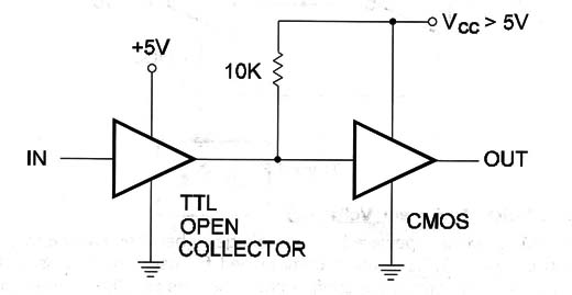
The power-supply voltage for the CMOS block must be higher than 5V.
CMOS to TTL (5V)
Figure 4 shows how a CMOS circuit can drive a TT'L input when both are supplied from a 5V source.
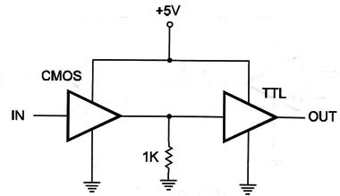
The resistor acts as a load for the CMOS output.
CMOS to TTL (Different Voltages]
If the CMOS block is powered with a voltage higher than 5V, the correct way to drive a TTL circuit is shown in Figure 6.
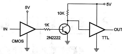
The transistor can be replaced by any general purpose NPN transistor, such as BC548.
CMOS to TTL Using a CMOS Buffer
Another way to drive a TTL input from a CMOS output is shown in Figure 7,
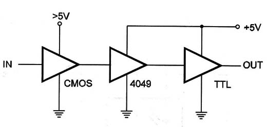
A buffer-inverter of the 6 existing in a 4049 IC is used in this configuration.
The buffer-inverter is powered from the same 5V supply that powers the TTL gate, and the CMOS block must be powered from a voltage source higher than 5V.
Operational Amplifier to CMOS (Same Voltage)
Operational amplifiers of voltage comparators can drive a CMOS stage using only a 10 k ohm resistor, as shown in Figure 8.
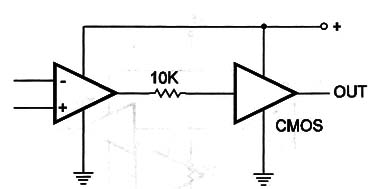
This configuration is valid if the voltage sources are the same for the two blocks.
Operational Amplifier to CMOS (Different Voltages)
The circuit shown in Figure 9 is used to drive a CMOS input from an operational amplifier or a voltage comparator and they are powered with different Voltages.
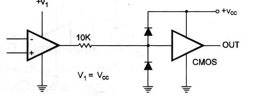
The diodes are used to protect the CMOS inputs. Any general-purpose silicon diode, such as the 1N914 or 1N4148, can be used in this task.
TTL to CMOS Using Optocoupler
Our last circuit is suggested for use to drive CMOS inputs from TT'L outputs using an optocoupler.
The configuration shown in Figure 10 has a principal advantage of isolation between the circuits.
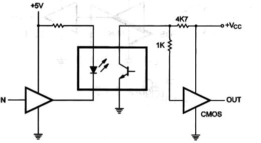
The optocoupler can be a 4N25 or any equivalent.
The resistor without indicated value depends on the current in the LED of the optocoupler.


