

The field-effect transistor can be of two types: enrichment and depletion, which symbols are shown in Figure 1.
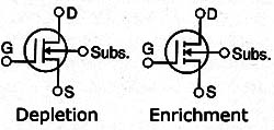
In both types, the current between the drain and the source is controlled by the voltage applied to the gate (gate). Note that in some cases a fourth terminal connected to the substrate is added. Although their electrical behavior in a circuit is the same, the way to test them is different.
We use to test these common analog digital multimeters components in a range Rx 100 and measure the resistance between its terminals. The procedures with the interpretation of the results are given below:
Depletion MOSFET
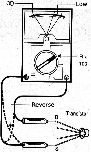
Using an multimeter in the R x 100 scale measure the resistance between the drain and the source in both directions, that is, first do a reading and then rereading reversing the test leads as shown in Figure 2.
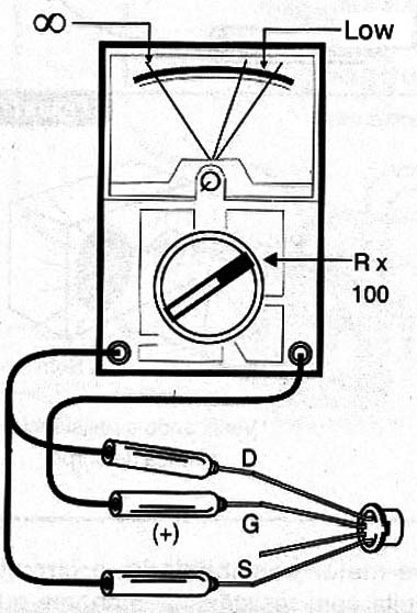
The two resistance readings in this test must be equal. Then connect the tip of the positive meter to the gate. Now, touch the negative end first into the proben, measuring the gate-drain resistance and then the source terminal, measuring the gate-source resistance, as shown in Figure 3.
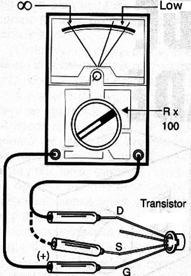
The two readings should be near infinite resistance, or open circuit. If the transistor has a substrate terminal, connect the black tip to the substrate terminal. Measure the resistance between the substrate and the drain and, furthermore, between the substrate and the source. The measured resistance should be infinite, as shown in Figure 4.
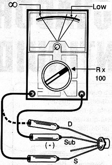
Reversing the leads in the two previous measures must find a low resistance, something around 1 k Ω.
Enrichment MOSFET
Again, with the multimeter in Ω x 100 resistance scale, measure the resistance between the drain and the source in both directions, as shown in Figure 5.

The two measures should indicate an extremely high resistance, close to infinity. Then connect the tip of the multimeter positive test in the holds of the transistor terminal. With the negative end measure the resistance between the gate and the drain and between gate and on the source. The two resistors, as shown in Figure 6, shall indicate an infinite resistance.
Disconnect the negative terminal of the gate and connect it to the substrate terminal. Measuring the resistance between this terminal and drain and then source, the readings should be infinite resistance.
Now, connect the tip of positive proof to the substrate and measure the resistance between the drain and the substrate and then between the source and the substrate. The two resistances must be infinte. Reversing the leads we should have a measure of low resistance of 1 k Ω order.
Different results
For all tests a low resistance reading which should be high indicates a transistor shorted. A resistance in the order of a few hundred kilΩ or a few megΩ which must be very high indicating a transistor with leak.
We also note that the low resistance indicated in the test may have different values from those indicated, depending on the type of component. A very high resistance which should be low, indicating an open transistor. Note that these are static tests, revealing nothing about the fact that the transistor be working or not. It only indicates that the component structure is not damaged.


