

Bridges are circuits that have a state of equilibrium when certain conditions of its elements are met. Using the known values of components in a bridge can determine the values of others which are unknown. Thus, using appropriate bridges can determine the value of resistances, capacitances and inductances.
Among the best known bridges, Wheatstone bridge stands out because it uses only resistors and is just used for determination of resistance.
The Wheatstone bridge has the basic configuration shown in figure 1.
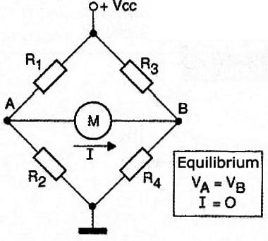
As we can see, this bridge has a voltage source that feeds a null detector or balance that is normally a milliammeter or other equivalent, according the current intensity that is expected in the circuit.
The condition for not circulate current whatsoever between points A and B where the detector instrument is connected is that the voltage between these points are equal and this occurs when the two pairs of resistors that form voltage dividers to points A and B have the same voltages. This will occur just as the following ratio of values between the resistors is met:
R1 / R2 = R3 / R4
When this occurs, we say that the bridge is in balance.
But what has all this to do with the measurement of electrical quantities or just resistance?
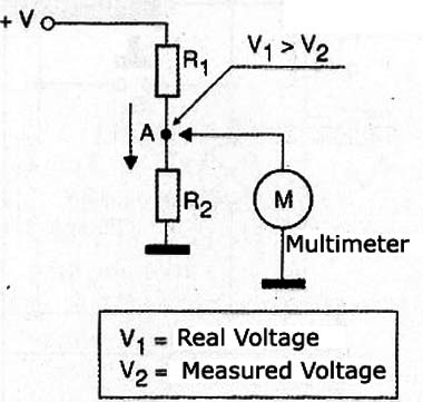
One of the critical points of electronic measures is the fact that, when introduced a measuring instrument in a circuit to perform, for example, a measure of stress, the presence of this instrument changes the measured quantity.
Thus, as shown in Figure 2, when using a common voltmeter to measure the voltage at point A of the circuit, the meter is connected in parallel with the circuit deriving a certain power, or carrying the circuit which is under measurement.
This means that the voltmeter "steals" circuit power to function and it changes the measure itself. We can say that the actual voltage at point A is greater than the one we found when we turn on the voltmeter and therefore he accuses.
One way to obtain a reliable measure of a quantity, for example, a resistor would imply that the instrument would not have to "steal" no power circuit and this can be achieved precisely by means of a bridge.
f we remember that at the moment when the tip is balanced by current does not flow in any instrument and so this instrument does not "load" the circuit, we have the optimum configuration for the measurement.
But how can this be done?
The simplest case to be explained is precisely the Wheatstone bridge.
As we have seen the balance in this bridge occurs just as the resistance of its branches maintains a certain well-defined relationship.
Thus, if we fix two resistors of this bridge, for example R1 and R2 and R3 variable resistor Rx can be determined accurately.
For example, if R1 and R2 are equal, balancing the bridge will be obtained only when R3 is equal to Rx. Calibrating precisely Rx (which may be a precision potentiometer) is easy to measure resistances with this feature.
In practice the bridges have a set of resistors that can be switched depending on the range of magnitude of the resistance being measured.
These variable resistors (potentiometers) are connected to a selector and the balance of pot runs on a graduated scale precisely, as shown in Figure 5.
Although digital multimeters are very accurate and have a large input resistance "not loading" circuits in testing the Wheatstone bridges can still be found in laboratories, especially in schools where its working principle is studied further.
In our project we will have a simplified version of a bridge, but it is nevertheless to be functional.
HOW IT WORKS
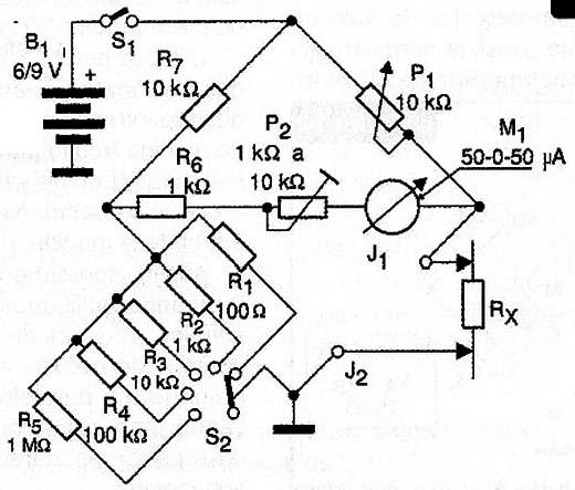
Our bridge uses different resistance values can be selected such that it is capable of measuring resistances on various tracks.
If, through the selector switch R5 we select to enter the circuit, we can see that R5 is 10 times smaller than R2.
This means that the other branch of the bridge will be balanced by P1 and only P1 and Rx maintain the same relationship. This means that with P1 = 10 k, the balance point is found when Rx is between 0 and 1 k Ω.
Likewise for the other resistors, allowing resistors always measure in the range of values of the selected resistor. For example, if we put the key in R8 can measure resistance from 0 to 1 M Ω.
The P2 pot only serves to adjust the sensitivity of the null indicator so that it is not driven by a very strong current when the adjustment potentiomete is not in its extremes.
The circuit can be powered by DC voltages from 6 to 9 volts and its consumption is not the highest, since it does not stay on for long in each measure.
ASSEMBLY
In Figure 4 we have the complete diagram of our Wheatstone bridge.
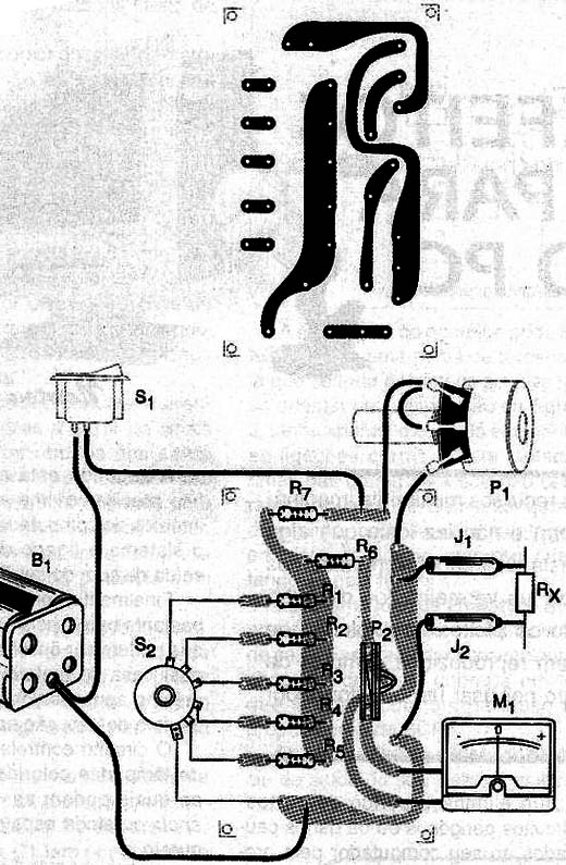
Although the case of an experimental setup that may be made in bridging or terminal array contacts, nothing prevents readers who desire to have a final assembly using a printed circuit board. The pattern of this board is shown in figure 6.
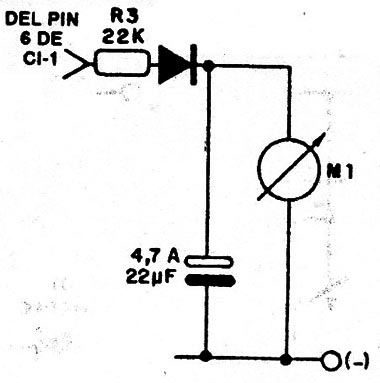
The resistors are all 1/8 watt or higher and the instrument is a microameter type with zero at the center of 50-0-50 scale µA found in ancient recorders and even other devices such as battery charge indicator.
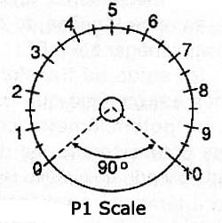
The potentiometer P1 must be linear good quality and performing a precise scale it is important for the measures, as shown in Figure 7.
To connect a (Rx) connection can be done or by two terminal pieces of wire with alligator clips.
The scale itself connection of resistors (R4 to R8) may be made with an alligator clip, thereby saving up of a selector switch 5 x 1 pole positions that is a component not easy to be obtained. For the batteries should be used a suitable support.
PROOF
To prove plug between J1 and J2 a known value resistor and throw the food.
Adjusting P1 must reset the indication of the instrument at the point of scale to match the resistor under test.
Set P2 to not having the pointer instrument hitting the ends of the scale when the Rx resistor is removed from the circuit or when the unit is turned on.
USE
To use if you have an idea of the resistance of the order of magnitude that will be measured, select a selector switch position according scale. Otherwise, start with the center position.
Always work with the circuit to be measured resistance, if not an isolated component, disconnected from their food.
Connect the resistor or circuit in the Rx terminals and then adjust at P1, obtain the balance (zero indication on the meter). If not, change range.
Then just read the resistance value measured at the potentiometer scale. The accuracy of the measurement depends on the accuracy of the pot and the scale itself.
Resistors (1/8 W, 5%)
R1, R5 - 1K Ω
R2, R6 - 10 K Ω
R3, R3 - 100 Ω
R7 - 100k Ω
R8 - 1 M ohm
P1 - 10 k Ω - linear potentiometer
P 2 - k 1 k Ω to 10 Ω - trimpot potentiometer or
Miscellaneous:
S1 - Single switch
M1 - 50-0-50 µA - microamperimeter
B1 - 6 or 9V - batteries or battery
Printed circuit board, battery holder, terminals, button scale for the pot, box mount, wire, welding, etc.


