In our books "The Secrets of Using the Multimeter", "Repair Everything" and "How to Test Components" (soon in English) we describe dozens of utilities for the multimeter and how to use what we consider the most important of all electronic tools.
Nowadays we can buy multimeters with extremely cheap prices, which means that it is not only essential but also very affordable.
No one who intends to practice electronics should be without a multimeter, no matter how simple it may be.
In this article we will describe some important and unusual uses for the multimeter.
We recommend that the reader has a multimeter at least 2000 Ω/volt of sensitivity, so the described tests can be performed accurately.
a) Discovering the impedance of a Speaker
Old loudspeakers or even purchased at a component store can come without the impedance indication which can prevent its use in a more critical project.
The process we describe below allows you to discover the impedance of a small speaker.
So we need a resistor of 18 Ω or 22 Ω x 2 W and a transformer having a secondary voltage of 6 V with 200 to 300 mA of current.
Connecting the resistor in series to the unknown impedance of the speaker, we apply a signal of 60 Hz (*) and it reproduces a rumble (which works to prove that it is good).
Figure 1 shows how the resistor and the speaker are connected and how to connect the multimeter to an AC low scale to do the measurements.
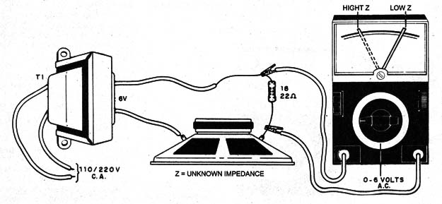
The resistor and the loudspeaker form a voltage divider which on one side has the resistance of the resistor and on the other the impedance, so the formula of Figure 2 can be used to calculate it.
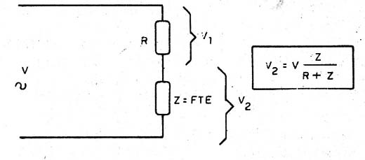
In general, we can say that for a 4 ohm speaker the reading in a multimeter will be approximately 5 V and if it is 8 Ω approximately 4.5 V.
It will be like having a known impedance speaker to compare.
(*) We cannot associate the measured values ??to the actual impedance, because it is not specified in most of the speakers for a frequency of 60 Hz, however the procedure can help, by comparison.
b) Values of Ceramic Capacitors
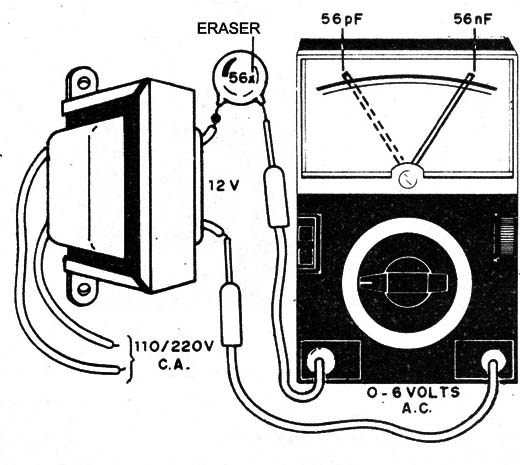
The same idea of a capacitive divider works to determine the values ??of capacitors as shown in Figure 3.
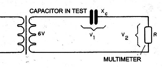
To do so we use a transformer with a secondary of 6 to 12 V, current from 100 to 500 mA and a multimeter in a low range of alternated voltages, as shown in Figure 4.
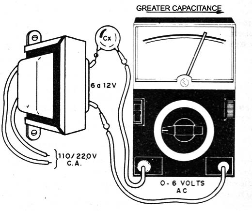
Then we use the internal resistance of the multimeter to make the divider.
With an analog multimeter of 10 k Ω/volt we will already have a voltage reading for this test.
The digital multimeters in general have a capacitor test feature and in this test it does not work due to its very high input resistance.
A problem which happens with many electronics practitioners is to confuse a capacitor of 56 pF with one of 56 nF, for example.
The markings can be confusing in some cases like 5,6p and 5,6P which leads to the malfunction of a circuit that uses these components.
One way to know the value is by comparison, based on a capacitor of a known value, for example, 47 nF.
As shown in Figure 5, the reading of 56 nF is closer to a 47 nF than a 56 pF.
Oscillators Analysis
We can verify if a high-frequency oscillator is oscillating, using a pick-up coil, as shown in Figure 6.
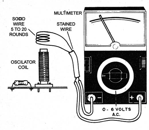
Just approach a common hardwired coil to the oscillator coil and connect it to the multimeter on a low scale of alternating current in order to detect the oscillator signal.
c) Testing FETs
For the test of JFETs or FETs of junction we start from the structure of this component and its equivalent circuit with diodes, shown in Figure 7.
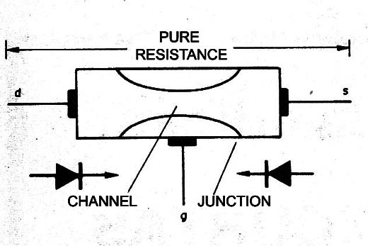
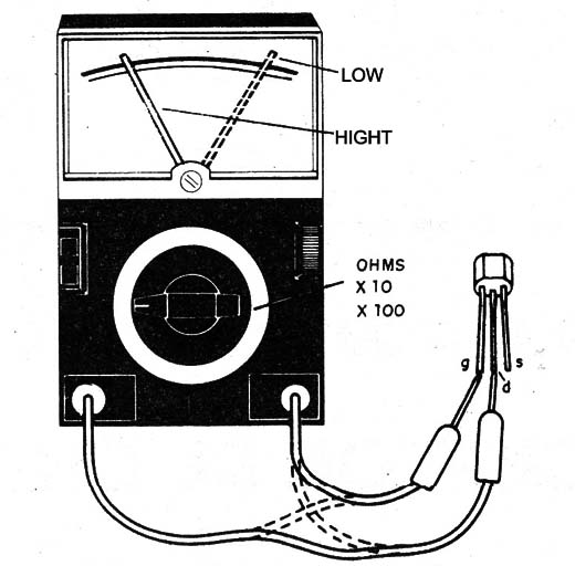
We see then that between the drain and the source we have a relatively low pure resistance, as shown in Figure 8.
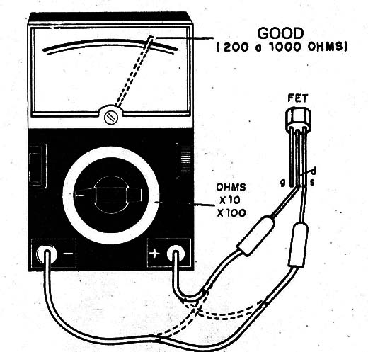
Between the gate and the drain or the gate and the source, the resistance is low in one direction and high in the opposite direction.
In Figure 9 we show what happens.
Conclusion
There are many other component tests that can be done with the multimeter and they are described in our books.
We also have several articles on the website about this subject and which should be consulted if the reader does not find in this article the procedure he/she is looking for.


