

A signal tracker is used to check the presence of radio (RF) and audio (AF) signals in electronic circuits. We use a signal tracker to detect bugs in radios, amplifiers, recorders, tuners, intercoms, oscillators and many other devices.
The follower we describe can work with either high frequency signals, i.e., radio frequency or RF, as well as with low frequency or radiofrequency signals, abbreviated as AF (or BF in some cases).
The follower uses only two battery cells and has two transistors as active elements.
These two transistors provide the circuit with an excellent sensitivity which allows to detect the weaker signals that are found in the circuits analyzed.
How it works
What we have, basically, is a sensitive audio amplifier with two complementary transistors that directly drives a small speaker.
At the input of this amplifier, we can directly apply the low frequency signals (audio) that will be reproduced in the loudspeaker.
To work with RF signals (radiofrequency) we need a detector that is a general purpose germanium diode.
We use the germanium diode to work with signals of less intensity than silicon. While germanium diodes start driving at just 200 mV, silicon ones need at least 600 mV.
The current consumption of this circuit is very low which means excellent durability for the used batteries.
Assembly
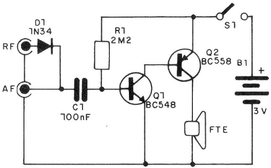
In Figure 1, we give the complete circuit of our follower, observing the existence of two inputs: one for audio and another for RF.
In Figure 2, we have its assembly realized in a bridge of terminals, which must be installed in a suitable box.
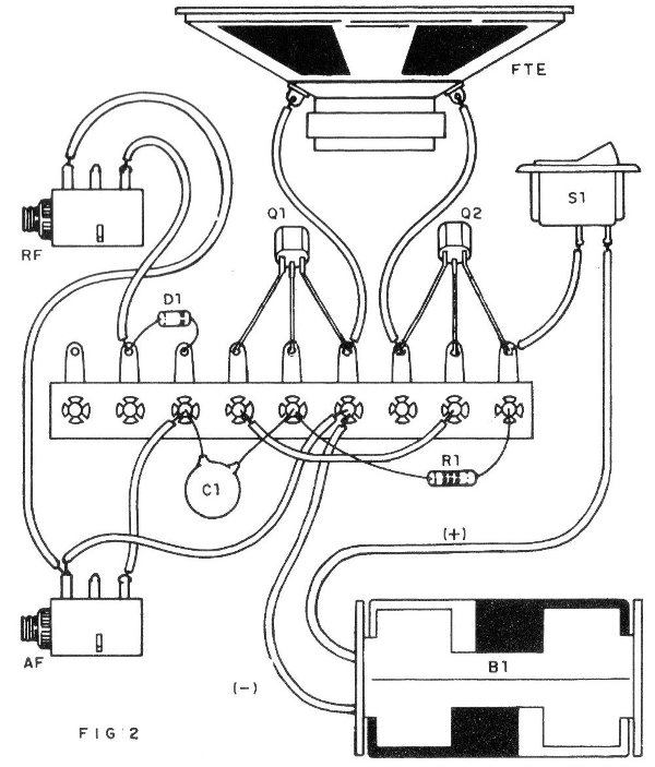
Assembly is very simple and the only basic care that is necessary is to observe the positions and polarities of some components such as transistors, diode and power supply.
The resistor can be 1/8 W or 1/4 W and the capacitor can be both ceramic and polyester.
It will be interesting to use a good quality speaker at least 10 cm in diameter for best performance.
Upon completion of the assembly, the operating test is immediate.
Test and Use
A very versatile probe is made as shown in Figure 3.
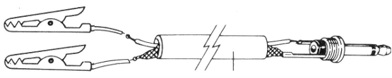
We use two claws, one for the connection to the ground which can be the negative of the device in test and the other for the connection to the point where the test signal is withdrawn.
To run the test, pick up a portable radio and turn it on.
Pressing the live probe (red) on the volume control and having the black (negative) probe attached to the negative of the power, as shown in Figure 4, the audio signals must be reproduced.
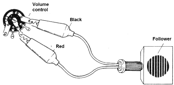
Note that in this case we are working with audio signals.
If the signal is taken to test before the detector, then it will be RF, and the other input must be used.
The device testing was done by tracking the signal. Do with the follower the same path that the signal amplifier should make, noting its presence in the various points. The moment it breaks down or disappears we will have reached the problem stage.
Tests on radio devices, amplifiers, etc. are made by verifying the presence of signal in the transistor bases and collectors if they are connected to the common emitter configuration, or to the base and emitter if they are connected to the common collector configuration, as shown in Figure 5.
Q1 - BC548 or equivalent NPN transistor
Q2 - BC558 or equivalent PNP transistor
D1 - 1N34 - germanium diode
R1 - 2M2 or 2M7 - resistor (red, red, green or red, violet, green)
C1 - 100 nF - ceramic capacitor
87 - 3V - 2 small battery cells
FTE - 4 or 8 ohm x 10 cm speaker
Miscellaneous
General switch (S1), terminal bridge, mounting box, holder for two small batteries, shielded test lead, plug and jack, alligator clips etc.


