DC motors are formed by one or more coils having a low resistance, which basically depends on their power and drive voltage.
In Figure 1, we have the symbol and aspect of this type of component.
Their trigger voltages typically range from 1.5 to 48 V and currents between 5 and 500 mA. This results in coil resistances between a few ohms and close to 500 ohm at most.
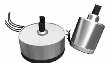
The step motors are basically of two types, shown in Figure 2.
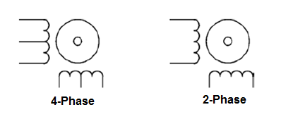
The motor type determines the number of coils. These motors typically have 12 V coils with currents ranging from 50 to 500 mA.
What we should test
The basic test we can do is to check the continuity of the coil, both for common DC motors and for step motors.
However, additional tests, such as those which allow us to evaluate the drained current, torque, nominal voltage, and other characteristics can be performed.
Instruments Used in the Test
Continuity Tester
Multimeter
Adjustable power supply (0-12 V x 1 A)
Also we can indicate the use of mechanical instruments like the dynamometer for the measurement of the torque or even the stroboscope, oscilloscope with special arrangements and frequency meters for the measurement of the speed (rpm).
Which Motors Can Be Tested
DC motors and step motors from 1.5 to 48 V can be tested with currents in the range of 10 mA to 1 A typically.
For step motors, the two- and four-phase types can be tested.
Also included in the tests are engines which have reduction systems (reduction boxes).
Alternating current motors for 110 V or 220 V voltages can also have their coils tested for continuity.
Procedure
1. Test of continuity of the windings
This test does not reveal short windings. For this purpose, in some cases, functional tests or tests similar to those described for coils may be performed.
a) Disconnect the motor terminals of the circuit in which it is located.
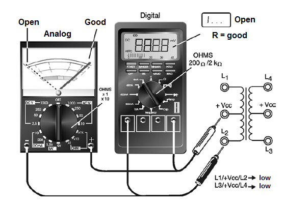
b) Set the multimeter to a low resistance scale (x1 or x10) by resetting it. The continuity tester shall be capable of indicating continuity with resistors from 0 to 1000 ohm.
c) Push the test leads of the multimeter or continuity tester into the terminals of the motor under test.
d) If it is a stepper motor with several windings, each one must be independently tested and identified.
In Figure 3, we show how to perform this test.
Interpretation of the Test
An engine that has its windings in order should have low resistance (or continuity in this test). A high resistance (above 10 k ohm) indicates that the winding is interrupted.
If a step motor has one of the windings interrupted, it can no longer be used in its basic applications. We note that this test does not reveal whether one or more motor windings have short circuits.
The winding resistance can serve as a parameter to obtain the current that the motor drains in the short-circuit condition.
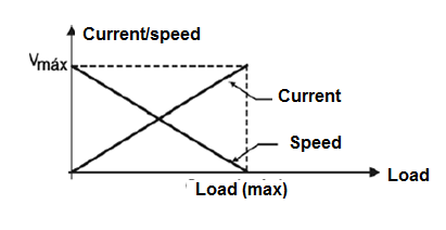
Remember that in a normal operation, the current will always be less than the short-circuit current depending on the load, that is, the force it is exerting. In Figure 4, we have a graph showing the typical behavior of a DC motor.
1. Determination of consumption
As can be seen from the graph of the previous figure (4), the current drained by a motor depends on its speed, which also depends on the load applied.
We can measure this current with the arrangement shown in Figure 5 where a multimeter is used in the current scale or an ammeter connected in series with the motor.
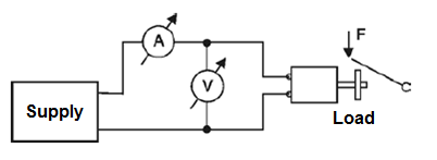
What we do is to feed the motor with the nominal voltage and charge it so that it exerts the force that normally need in the application for which it is intended. Just read the current intensity on the instrument.
Other Tests
Other important features can be determined in common and step motors through relatively simple procedures.
1. Speed (rpm)
The speed of a DC motor depends on the voltage applied and the load and can vary over a wide range of values if there are no regulator circuits.
In the case of a step motor, the speed depends on the frequency of the applied signals and the number of steps. Thus, it can be determined from the knowledge or measurement of that frequency.
We can use a frequency meter or an oscilloscope to determine the speed of a motor, starting from the circuit shown in Figure 6.
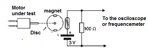
In a simpler configuration, we attach two small magnets to a disk (we use two to balance the disk) that will be attached to the motor shaft.
That way we will have two pulses generated on a reed switch at each turn of the motor shaft.
Simply apply the generated signal to the input of an oscilloscope or a frequency meter to obtain the motor rotation.
A frequency of 60 pulses per second, or 30 revolutions per second, if we use two magnets, will correspond to 30 x 60 = 1 800 revolutions per minute or r.p.m.
For greater speeds, where the reed switches may not switch, we have an alternative circuit using a perforated disk, shown in Figure 7.
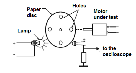
The sensor is a phototransistor, coupled to a simple circuit capable of generating pulses which excite a common frequencymeter or even an oscilloscope.
Other possibilities include the use of magnetic or Hall effect sensors.
2. Torque
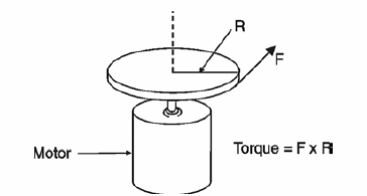
For an engine, torque is defined as the force x distance product where the force is applied externally at the end of a lever or gear attached to the shaft and the distance is measured from the center of the shaft to the point at which that force is applied , as shown in Figure 8.
In order to measure this force, we can use the arrangement shown in Figure 9, which allows us to determine the torque of a motor according to the applied voltage and current.
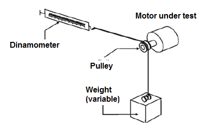
Note that the system allows different torques to be required from the motor, which allows us to associate them with the speed at which they are met.
Observations
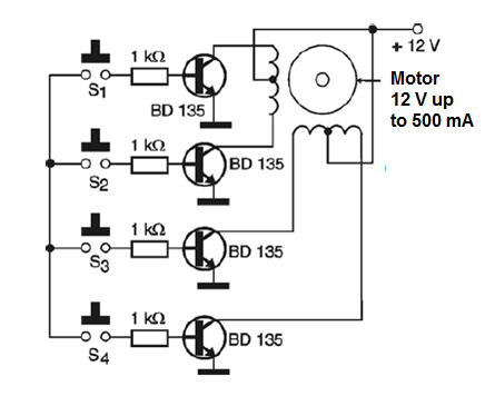
Step motors require the use of special driven circuits for their test. In Figure 10, we give one of these circuits that even allow us to identify the terminals or the sequence of phases for the trigger.
