

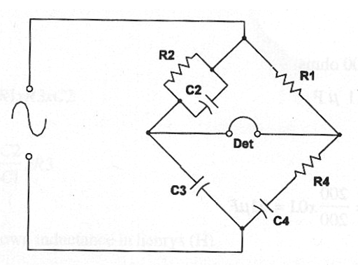
This bridge is used to measure inductances and capacitances. The input is a signal generator with frequency chose according the magnitude of the capacitance or inductance to be measured. The basic circuit to capacitance measurements is shown in figure bellow.
Formula:
When balanced:
C4 = (R2 / R1) X C3
and
R4 = (C2 / C3) x R1
Where: C2 and C3 are the capacitances in the arms (one of them variable) in farads (F)
C4 is the unknown capacitance in farads (F)
R4 is the unknown resistance in ohm (Ω)
R1 and R2 are the resistances in the arms (one of them variable) in Ω (Ω)
Application example:
A Schering Bridge is balanced when R1 = R2 = 200 Ω and when C1 = C3 = 0.1 µF. Determine the unknown capacitance (C4) and the associated resistance (R4).
Data:
R1 = R2 = 200 Ω
C1 = C3 = 0.1 µF
Determining C4:
C4 = (200 / 200) x 0.01 = 0.1 µF
Determining R4:
R4 = (0.1 / 0.1) x 200 = 200 Ω


