

NICAD CHARGER
Nicad's rechargeable batteries or just rechargeable batteries are the ideal power source for mechatronic and robotic projects. However, these batteries need to be recharged.
The very simple charger we describe is for small, medium and large cells providing a load current of the order of 20 to 50 mA in the 110 V network.
The circuit is economical for not using transformer since the reduction of the current is made by a lamp of 5 to 15 watts for the network of 110 V.
The rectification is done by a diode 1N4004 and the final reduction by a resistor (R1) that can have its value changed according to the types of batteries or batteries that must be recharged.
We can charge from 1 to 4 small, medium or large batteries with this unit, for times between 5 and 16 hours, according to the manufacturer's indication.
The reader can use the Meter to check the actual charge current according to the tolerances of the components and adjust R1 to get the current you need for the specific type of batteries you use.
The polarity of the connection of the diode and the battery holder is essential for proper operation of the device. By connecting two 4-cell batteries in series, we can charge up to 8 small, medium or large batteries.
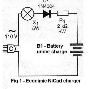
In Figure 1 we have the complete diagram of the loader.
In Figure 2 we have the actual arrangement of the components for this assembly.

Of course, components should not be exposed to an accidental touch that would cause dangerous shocks. The assembly should be in a closed plastic box. The appliance is not isolated from the mains.
First, place the batteries you want to charge into the cradle and then plug the power cord into the cradle. The lamp should light up when charging.
If the lamp does not light, turn off the power and adjust the batteries in the holder as they may be in poor contact.
The brightness of the lamp should be slightly less than normal during the charge. If any battery in the recharging process does not store energy, it is a sign that it may be damaged. Do not use it together with those in good condition any longer.
D1 - 1N4004 or equivalent - silicon diode
X1 - 5 watts at 15 watts x 110 V - common lamp
R1 - 2k or 2.2k ohms x 5 watts - wire resistor
B1 - Batteries to be recharged - see text
Miscellaneous - Battery holder, terminal bridge, lamp socket, power cable, assembly box, wires, welding, etc.
CMOS TOUCH KEY
One touch on the sensor element X1 and the relay closes its contacts, remaining like this for a time interval determined by the setting of P1. Motors and miscellaneous devices like solenoids and electromagnets can be activated in robotics and mechatronics projects.
We can also use this circuit in alarms, alarm deactivation systems, door opening or in the lamp timer.
The standby current of the circuit is very low, which allows the use of batteries as its power supply. The relay, on the other hand, can control powerful loads, even connected to the power grid.
The sensitivity of the circuit is great, allowing the slightest touch on the sensor to trigger it. The sensor can be from a single bare end of a wire to a metal board, which should be insulated by a plastic or wooden support base. A printed circuit board up to 15 x 15 cm can be used as a sensor.
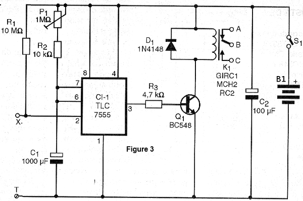
In Figure 3 we have the complete diagram of the device.
The arrangement of the components on a printed circuit board is shown in Figure 4.
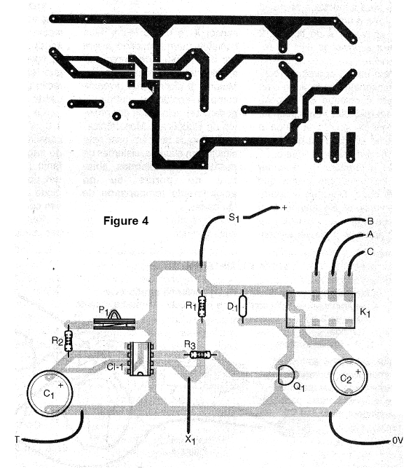
The integrated circuit must be installed in a DIL socket for extra safety. The relay can be either of the type with the base provided in the figure or equivalent since they have supply voltage (coil) according to the one used in the design.
The resistors are all 1/8 watt or larger and the capacitors must have working voltages of 6 V or more. P1 can be either a trimpot or a common potentiometer. The diode accepts equivalents as well as the transistor.
4 alkaline batteries or a power supply can be used.
The operating test is simple: turn on the device and the adjust P1 for a minimum time interval (smaller resistance). Touching X1 and T at the same time with your fingers the relay should close its contacts remaining so for a few seconds. Then the relay disarm and the circuit can be triggered again with the same procedure.
To use the circuit with maximum sensitivity connect the T point (ground) at any point that has contact with a ground such as a metal door or window, or even a metal faucet.
Proving it works, if there is instability, reduce the value of R1. Then set P1 to the desired triggering time and connect to the relay contacts the device to be controlled.
Semiconductors:
CI-1 - TLC7555 - CMOS integrated circuit
Q1 - BC548 or equivalent - general purpose NPN transistor
D1 - 1N4148 - general purpose diode
Resistors: (1/8W, 5%)
R1 - 10 M ohms - brown, black, blue
R2 - 10 k ohms - brown, black, orange
R3 - 4.7 k ohms - yellow, violet, red
P1 - 1 M ohms - trimpot or potentiometer
Capacitors:
C1 - 1000 uF/6 V - electrolytic
C2 - 100 uF/6 V - electrolytic
Miscellaneous:
K1 - General Purpose 6 V Relay - Metaltex or equivalent
S1 - Simple switch
B1 - 6 V - 4 common batteries
Printed circuit board, assembly box, battery holder, integrated socket, wires, welding, etc.
SOLID STATE RELAY
DC loads up to 2 amps as voltages from 6 to 15 volts can be found for this high sensitivity solid state relay. These loads can be bulbs, motors, solenoids, heating elements, electromagnets, etc. Common relays can be replaced by this circuit in many robotic and mechatronic projects.
The sensitivity of the circuit is great enough for sensors such as phototransistors, LDRs, thermistors, etc to be used directly to control high current loads.
The sensitivity adjustment is done at P1 since the circuit based on a power field effect transistor (power FET) is extremely sensitive.
The transistor will conduct when the voltage between E1 and E2 becomes positive enough to saturate it. A resistive sensor will be connected between E1 and the positive supply. The circuit can also be controlled directly by TTL and CMOS outputs, which allow its use without interfacing robotics and mechatronics projects with computers.
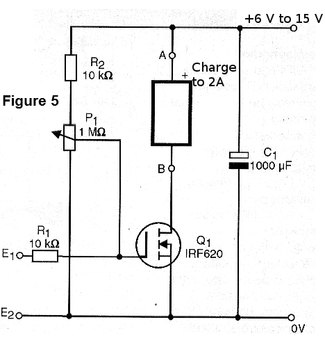
In Figure 5 we have the complete solid state diagram for currents up to 2 amps.
The arrangement of the components on a terminal bridge is shown in Figure 6.
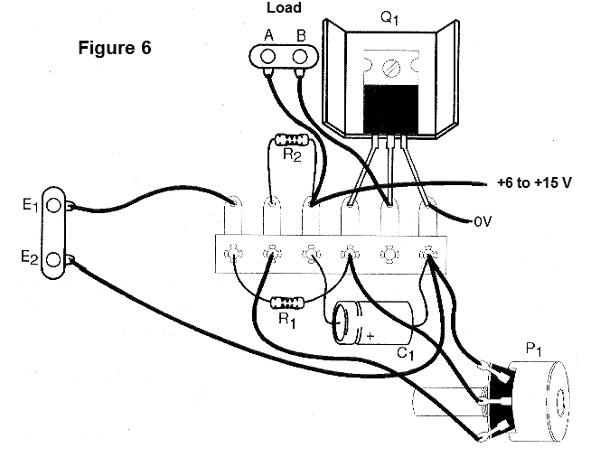
The transistor has a heat radiator, mainly used for currents above 1 amp. The resistors are 1/8W or higher and the capacitor develops a working voltage slightly higher than that one used by the power supply.
At points A and B we connect the load to be controlled between E1 and E2 or even E1 and the positive supply the sensor or a driven signal source of the circuit.
If the load is inductive (motors or solenoids) it is convenient to connect a protection diode in parallel, polarized in the inverter direction (cathode or range) connected to the positive of the power supply.
Checking the operation of the relay we can use it.
Semiconductors:
Q1 - IRF620 or equivalent - any power FET with more than 2 A of draining current
Resistors: (1/8 W, 5%)
R1, R2 - 10 k ohms - brown, black, orange
P1 - 1 M ohms - potentiometer
Capacitors:
C1 - 1000 uF - electrolytic
Miscellaneous:
Antenna / ground terminal bridge for input and output, heat radiator for the transistor, assembly box, potentiometer knob, wires, welding, etc
LOCKED RELAY
We show in this circuit how to obtain the locking effect for a common relay. This effect consists of the following: When we energize the coil of a relay, it closes its contacts only while running. When the chain is cut the relay opens its contacts.
If we want to have the relay closed after the chain is cut off, i.e., if we want to lock the relay after it is activated, we need a special circuit.
The circuit we describe takes advantage of the NO contacts of a reversible two-contact relay (any type for 6 or 12 V is suitable for this application).
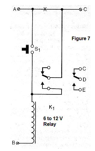
In Figure 7 we have the complete diagram of the relay with a “lock”.
In Figure 8 we have the actual appearance of the components in their connection to form this circuit.
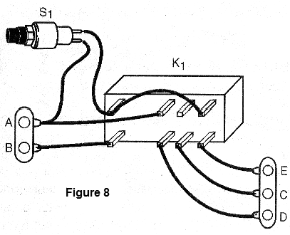
In this basic circuit, we feed the relay between A and B where we apply a voltage of 6 or 12 V depending on the type of relay used.
When we press S1 the relay closes its contacts and locks. Even after releasing S1 it remains with the contacts closed.
To disarm the relay, you must cut off the power for an instant.
An alteration option for the circuit to be able to operate with a voltage pulse is made as follows:
We have eliminated S1 by connecting this point directly to the input A of the command pulse. We connect the C point to the positive circuit supply.
A protection diode between A and the pulse input may be required depending on the application.
When we apply a pulse between A and the relay it triggers and it self-feeds via C.
To disconnect the circuit, the power must be interrupted for a moment in C. Another way to disconnect the circuit is to shorten the relay coil for a moment.
K1 - sensitive 6 or 12 V relay - any type
S1 - Pressure switch NO
Miscellaneous:
Terminal bridge, wires, assembly box, etc.
MOTORCYCLE ENGINE SOUND EFFECT
The movement of mechanical arms, robots and other automatisms studied in mechatronics is made by silent motors. In a demonstration, it may be interesting to have some kind of sound effect which mimics the noise of a motor in order to give more realism to the operation of such devices.
The circuit we propose is simple and can be powered with voltages from 3 to 6 volts. The efficiency of the circuit is very good and the small speaker can be built into the automation or installed in a suitable box.
The circuit also has a frequency adjustment, which serves as an accelerator for this effect and which can be within reach of the operator or even be coupled to some automatic triggering device.
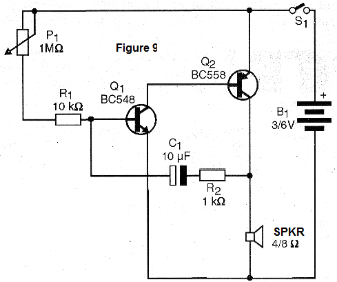
Basically, the design consists of an oscillator where the frequency is either determined by C1 (which can be changed) or by the settings of P1 (which acts as an "accelerator").
In Figure 9 we have the complete diagram of this apparatus.
In Figure 10 we show the arrangement of the components in a terminal
bridge which is the simplest and most immediate version mainly for the beginners.
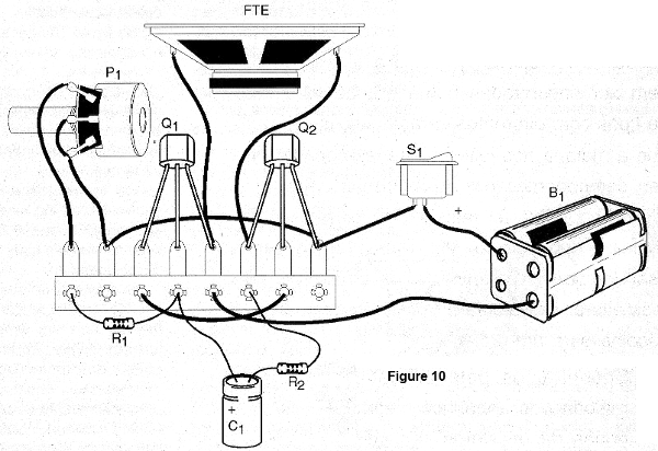
The transistors allow equivalent and even Q2 can be a BD136 or TIP32 and the 12 V powered circuit for higher power. In this case, however, power must come from a source or battery, since a simple set of batteries would not be able to supply the required energy.
The speaker can be from 5 to 10 cm with 4 or 8 ohms of impedance. The resistors are 1/8 W or larger and the electrolyte is 12 V.
To test the appliance, just turn on the power. Cracking should occur at a greater or lesser speed as we adjust the potentiometer. Adjust to get the sound equivalent to a motor.
After proving it is working, just install the set in a box and use the device in the best way, embedding it in your robotic or mechatronic assembly or wherever you want.
Q1 - BC548 or equivalent - general purpose NPN transistor
Q2 - BC558 or equivalent - general purpose PNP transistor
FTE - 4 or 8 ohms - small speaker
S1 - Simple switch - optional
B1 - 3 or 6 volts - 2 or 4 alkaline batteries - see text
P1 - 1 M ohms - potentiometer
R1 - 10 k ohms - brown, black, orange
R2 - 1 k ohms - brown, black, red
C1 - 10 uF / 12 V - electrolytic capacitor
Miscellaneous:
Terminal bridge, assembly box, two or four battery holder (optional), button for the potentiometer, wires, welding, etc.


