Counting circuits consist of bistable configurations called flip-flops and are available in the form of integrated circuits of several logic families. The TTL family, which is one of the most common and easy to use, has counting circuits that can be interconnected to count as many as we want.
Thus, working with integrated circuits such as the TTL family (Transistor-Transistor Logic) we can choose the functions we want and assemble digital devices of varying degrees of complexity. A particularly interesting integrated circuit of this family is the 7490 (almost all the members of this family start with 74, so it is commonly called the 74 or 74xx family).
This integrated circuit consists of a decade counter, that is, a set of flip-flops and other circuits that are capable of counting up to 10, or even making logical divisions up to 10. The output of this integrated circuit is encoded in binary, that is, BCD (Binary Coded Decimal).
Like any TTL integrated circuit, the standard family's 7400 works with 5 V power and has a maximum operating speed of the order of 18 MHz. That means it can count up to 18 million pulses per second without problems! Using two of these integrated circuits and one that produces slow counting pulses, we design a simple counter that the reader can assemble into a matrix of contacts to learn or teach some digital logic and binary numbering.
The 7490 in practice
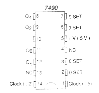
The integrated circuit 7490 has the appearance shown in figure 1.

All components, transistors, diodes, resistors, etc. which form this integrated circuit are part of a tiny silicon chip that is inside the plastic In-DIL (Dual In Line) wrapping that forms it. Access to the circuit is obtained from 14 terminals "or legs" which are always numbered from a mark in the order shown in the figure.
Depending on how we connect the "legs" of this integrated, it can behave differently by counting or dividing the input pulses by numbers between 2 and 10. The input of the pulses to be counted is made on pin 14 and the outputs Correspond to pins 12, 9, 8 and 11.
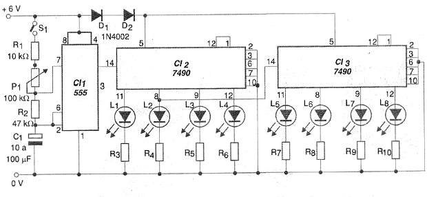
By connecting the circuit in the form shown in figure 3 , which corresponds to our circuit, the 7490 counts up to 10, providing at its four outputs electrical levels in torque. Thus, a voltage of 5 V corresponds to the binary digit "1" and a zero voltage, corresponds to the binary digit "0". The output terminals then have weights, which are studied in binary numbering.
If we have a sequence of pulses, as shown in the table below, they will turn on positive voltage levels, that is, when we have "1" and will remain erased at "0".
| Pulse | Q8 | Q4 | Q2 | Q1 |
| 0 | 0 | 0 | 0 | 0 |
| 1 | 0 | 0 | 0 | 1 |
| 2 | 0 | 0 | 1 | 0 |
| 3 | 0 | 0 | 1 | 1 |
| 4 | 0 | 1 | 0 | 0 |
| 5 | 0 | 1 | 0 | 1 |
| 6 | 0 | 1 | 1 | 0 |
| 7 | 0 | 1 | 1 | 1 |
| 8 | 1 | 0 | 0 | 0 |
| 9 | 1 | 0 | 0 | 1 |
When we arrive at the pulse node (9) the passage to the tenth turn to 0000 in the first integrated circuit and a pulse to the tens is produced. So just put another integrated then pin 14 used as the input of tens so that the count can be made up to 99. With yet another integrated circuit, it is possible to count up to 999 and so on.
Q8 has the corresponding LED weight = 8
Q4 has the corresponding LED weight = 4
Q2 has the corresponding LED weight = 2
Q1 has the corresponding LED weight = 1
Our Counter
In our practical assembly we will connect two integrated circuits 7490 so that one counts the units and the other of the tens.
A third integrated circuit acts as an oscillator to generate the pulses to be counted. In this case, we employ an astable stable circuit 555 at a very low frequency so that we can visualize the pulses produced. This frequency is determined both by the P1 setting and by the C1 capacitor which can have its value changed if the reader so wishes.
It is necessary to use a 555 in this circuit, because the 7490 only counts digital pulses, that is, rectangular pulses and a little bit connected directly in the entrance would not produce such pulses. A little piece has what we call a "peal", that is, it vibrates a little before closing and this vibration could be interpreted by the integrated circuit as more than one pulse.
An interesting idea is to adjust P1 of the oscillator to produce one pulse per second. This will cause the circuit to be used as a stopwatch from 00 to 99 seconds. Another possibility is to use a gate sensor that allows the circuit to generate a pulse whenever something passes in front of the sensor. It can be used to count people or objects.
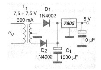
The power to the circuit must be made with a voltage of 5 V. In order to use a 6 V battery (4 cells) we put in series with the circuit a diode 1N4002. If the reader wants, you can mount a power supply like the one shown in the Figure 2.

ASSEMBLY
In figure 3 we have the complete circuit of our counter, noting that it uses 3 integrated circuits.

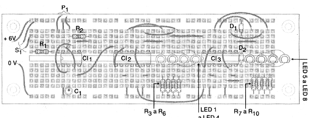
The assembly can be done in a protoboard, as shown in figure 4, since it is an experimental assembly.

In assembly, care must be taken with the position of the integrated circuits, diodes and LEDs because if any of them are inverted, the circuit will not work.
Test and Use
Turn on the power of the unit observing the polarity. If, when turning on the circuit some of the LEDs light up, indicating a count other than 0000 0000, simply turn off the terminals 2 and 3 of the 7490 and press them into the positive of the power supply. This will "reset" the circuit. Then just press S1 and set P1 to start counting.
Transversal Themes
Learning to read a number represented in binary form, converting it to decimal form is a topic of interest in high school (STEM programn) and technical education. It can be associated with the functioning of computers and help understand digital logic. In this way, the circuit we describe can be used as a working tool for binary number learning. The teacher can randomly generate a number in the counter and ask the student to make their conversion to the decimal equivalent.
We note that the counter described is BCD, that is, each 4-digit group counts up to 9. This configuration is different from a pure binary counter in which the 4 bits of each group count to 16. A pure 8-bit binary counter (8 LEDs would count to 255 and not only up to 99). One suggestion of work is precisely to explain this difference.
Semiconductors:
CI-1 - 555 - integrated circuit, timer
CI-2, CI-3 - 7490 - TTL integrated circuits
LED1 to LED8 - Common red LEDs
D1 - 1N4002 (see text) - silicon diode
Resistors: (1/8 W, 5%)
R1 - 10 k ohm - brown, black, orange
R2 - 47 k ohm - yellow, violet, orange
R3 to R10 - 470 ohm - yellow, brown, brown
P1 - 100 k ohm to 1 M ohm - common potentiometer
Capacitors:
C1 - 10 uF to 100 uF x 6 V - electrolytic
S1 – On/Off switch
Miscellaneous:
Protoboard, wires, 4 batteries and stand or power supply, etc.


