

The circuit works very simply: with the illumination of a sensor element, which in this case is an LDR, the motor starts up. To stop the motor simply cut the light on the LDR.
The circuit has two settings which allow the motor to operate in certain ranges of light intensities.
Depending on this adjustment, we can simply turn the motor on or off with the light, or vary its speed by varying the intensity of the incident light.
The circuit is designed in the basic version for 6 V motors with currents up to 500 mA. However, by changing the motor and the power supply, the circuit will operate with voltages between 3 and 12 volts without any modification.
Only in the case of motors having greater currents, the transistor Q2 will be provided with a heat radiator.
HOW IT WORKS
To obtain greater sensitivity from the circuit, the control current is amplified by two transistors in the Darlington configuration.
So, as of a very weak base current, which comes from the LDR, we can get the hundreds of milliamps needed to power the motor.
The sensor is an LDR. With the illumination of this component, its resistance decreases, going from a few million ohms in the dark to a few thousand, or even hundreds, of ohms into the light.
The circuit is sensitive enough that at maximum setting we can drive the motor simply by pointing the LDR at a candle many meters away.
The two trimpots (P1 and P2) serve to set the minimum and maximum points. We then set P2 so that the motor is at the threshold of operation when light is minimal.
Then we set P1 so that the motor has maximum speed at maximum illumination.
We then have the motor operating range according to the brightness range of the control lamp (or source).
ASSEMBLY
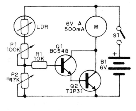
In Figure 1 we have the complete diagram of the system.
Our suggestion of assembly is based on a terminal strip that is shown in Figure 2.
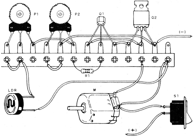
The LDR is of the ordinary round type. Nothing prevents the LDR connection wire to the motor control unit from being long.
The trimpots should be accessible to fit and the single resistor is not critical. In fact, its value can be between 2k2 and 33k, with no malfunctions.
Equivalents are also allowed for the transistors. For Q1 we have the following: BC237, BC238, BC547, BC107, AC187 etc. For Q2 we have the BD135, BD137, TIP29 etc.
The power will depend on the motor. Small motors can be used for a motor up to a 100 mA current. For motors of greater consumption we recommend the use of a source or medium or large batteries.
A recreational application of the project is shown in Figure 3, a small boat (to be used at night) which is controlled by a flashlight.
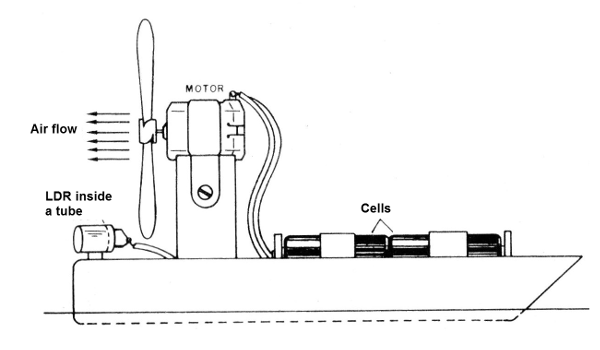
It is an "aeroboat" where the propulsion is done by a plastic propeller.
In order to increase the directivity of the sensor, we suggest the LDR to be built in an opaque cardboard tube with or without lens on the front. If the lens are used, the LDR should be close to the focus.
TEST AND USE
To test the appliance, cover the LDR and turn on the power. Then set P2 to stop the motor.
Then uncover the LDR and set P1 to have the maximum speed. If the light is too strong, there may be no sensitive adjustment of P1. In this case, if in practice the LDR is to work in strong light, replace P1 with a 470 k trimpot.
To use it you only need to point the LDR to the light source that must control the motor.
Depending on the application it may be necessary to change the polarity of the motor by inverting its wiring so that it rotates in the desired direction.
Note: In Figure 4 we give a suggestion of a different control by light which allows us to drive a toy hydroplane using a flashlight.
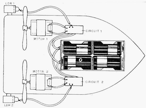
The motor that has the LDR brighter speeds up more and the boat tends to turn to one side or the other. Thus, by directing the beam of light to one LDR or to another, the operator can change the direction of the small boat.
Q1 - BC548 or equivalent - NPN transistor
Q2 - TlP31 or equivalent - NPN transistor
LDR - Common LDR
S1 - single switch
B1 - 6 V - 4 cells (see text)
M - motor up to 500 mA from 3 to 12V (see text)
P1 - 100k trimpot
P2 - 47k - trimpot
R1 - 10 k - resistor (brown, black, orange)
Miscellaneous: terminal bridge, assembly box, battery holder, wires etc.


