Counting circuits, consisting of many flip-flops, are available in several integrated versions. These versions belong to families such as the one called TTL. What characterizes the integrated ones of a family is that all have the same characteristics of input, output and power and so can be interconnected directly.
So, working in a family like the TTL (Transistor Transistor Logic), we can choose the different types (doors, counters, etc.) and easily gather them to form the digital device we want and even reach a degree of complexity which leads us to calculators and even computers.
One of the most interesting members of this family is the 7490 (almost all the members of this family start with the number 74). This integrated consists of a decade counter, i.e., a set of flip-flops and other circuits capable of counting numbers up to 10 or do divisions up to 10 and having an output encoded in binary.
Like all TTL it works with 5 volts of power and has a very high operating speed of 18 MHz. That means it can count up to 18 million pulses every second without problems!
Using two of these integrated and one more which produces the pulses for the count, we designed a simple circuit which the reader can build in its array of contact to learn a little of computer science, as it will be explained next.
7490 IN PRACTICE
7490 is an integrated circuit shown in Figure 1.
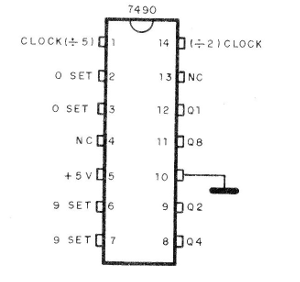
All components, transistors, diodes, resistors etc. which form these integrals are built on a tiny silicon wafer within a plastic housing of the component. Access to the circuit is done through 14 terminals which are always numbered from a mark in the order shown in the figure.
Depending on the way we connect certain terminals of this integrated, it can behave differently, counting or dividing the input pulses by numbers between 2 and 10.
The input of counting pulses is made at pin 14 and the outputs correspond to pins 12, 9, 8 and 11.
Connecting as shown in Figure 2, 7490 counts up to 10, providing torque (4 terminals) at the output. Thus, a voltage of 5V corresponds to "1" and a null voltage to "0".
The output terminals then have weights, as we have already studied in the binary count. If we have a sequence of pulses, as shown in the table below, levels will change by counting in binary.
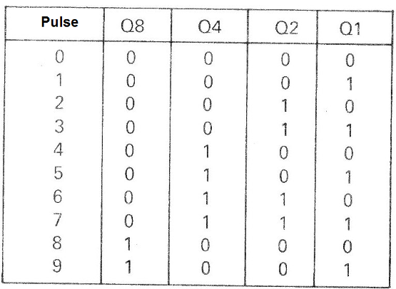
On the tenth pulse we return to the initial situation.
If you turn on LEDs as the final circuit shows, they will turn on positive voltage levels, that is, when we have "1".
This type of counter finds many applications in the computer science because it allows to register the numbers and even to carry out operations of sum. If we apply 10 pulses and then other 30, the LEDs will be lit in a setting that corresponds to 40 in binary!
ASSEMBLY
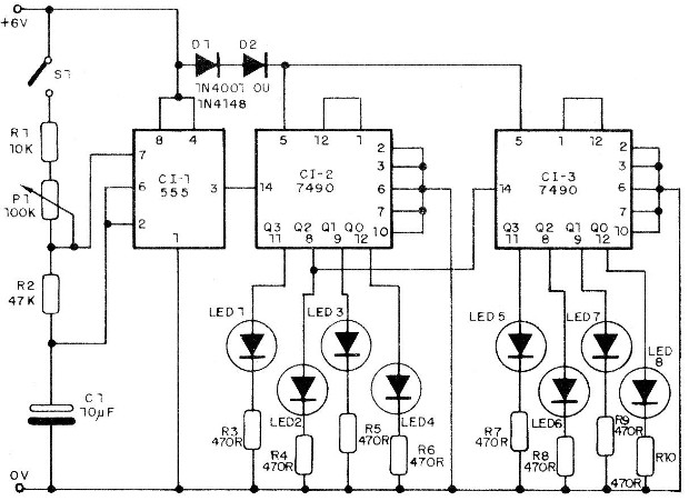
In Figure 2 we have the diagram of our counter, observing that it uses 3 integrated.
The assembly in the protoboard is shown in Figure 3.
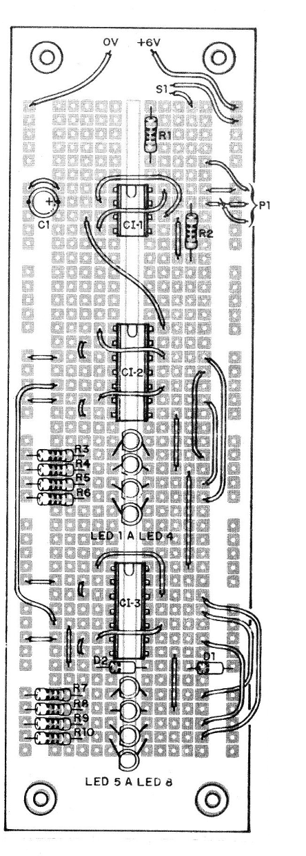
Observe carefully the position of all the integrated ones and mainly of the LEDs.
The 555 has the function to generate the pulses that will be counted, and in the trimpot P1 we can control its speed. If we adjust this component to one pulse per second we will have a stopwatch of up to 99 seconds.
The diodes D1 and D2 have the function to reduce by approximately 1.2V the 6V of the power supply, since the integrated ones operate between 4.8 and 5.2V approximately.
The resistors are all 1/8 or 1/4W and the capacitor C1 can have values ??between 10 and 100 uF for 6 V or more.
TEST AND USE
Turn on the unit, observing the polarity of the power supply (source or 4 batteries). If the LEDs light up, not indicating the 0000 0000, simply turn off the terminals 2 and 3 momentarily and press it on the positive of the power supply to reset the circuit.
Then just turn S1 on and set P1 to the binary count.
Cl-1 - 555 - integrated circuit
Cl-2, Cl-3 - 7490 - TTL integrated circuits
D1, D2-1N4148 or any silicon diode
P1 - 100k - trimpot or potentiometer
LED1 to LED8 - Common red LEDs
R1 - 10 k - resistor (brown, black, orange)
R2 - 47k - resistor (yellow, violet, orange)
R3 to R10 - 470 ohm - resistors (yellow, violet, brown)
S1 - Single switch
C1 - 10 uF to 100 uF - capacitor for 6 V or more - electrolytic
Various: contact array, 4 small batteries, wires, welding etc.