
Everything which escapes the normal is attractive, especially when it involves mystery or an unusual phenomenon. The magic bulb we are describing is an example: although it is plugged into the power outlet via a wire, like any ordinary bulb, there is no switch to turn it on or off. The process we use has nothing to do with the Age of Electronics, because it is exactly the same as the one used to light a candle: we lit it by using a match or lighter and turn it off by blowing.
Of course, by showing this to friends or to visitors at a science fair, you will have a very special attraction in the project, and the curiosity to know how it works can earn you a lot of good points. The circuit presented uses a common lamp from 5 W to 100 W and works on the 110 V or 220 V network. Its installation offers no difficulty even for the less experienced.
It is clear that the fire itself cannot ignite the filament of a common incandescent lamp, so we resort to some tricks which are also valid to turn off the device, since a blow cannot reach its interior beyond the glass bulb.
We use a circuit that "sees" the light of the match or lighter to establish the current through the lamp. This circuit is based on an LDR that will be built in a small hole pointed directly to the lamp and to the place where the match or lighter should be lit, as shown in Figure 1.
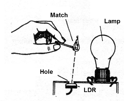
So, when lighting a match, its light hits the LDR and triggers the SCR which turns the lamp on. The P1 trimpot allows you to adjust the sensitivity of the LDR to ambient light.
Once the light comes on, its light will keep the SCR running, thus dispensing the lit match. This means that, once it is lit, the lamp feeds the circuit to maintain this condition.
To turn it off we have the second part of the trick: by placing your hands in a shell close to the lamp (do not touch it as it heats up), as shown in Figure 2, and at the same time by blowing off we interrupt the light on the LDR so that the SCR switches off.
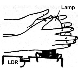
The lamp goes off, but whoever is observing the trick will not think that it was the shadow of the hand that did it, but the blow or the "choking" of the lamp!
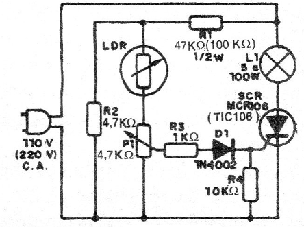
The resistor R1 together with R2 form a voltage divider which allows to obtain around 10 V for the LDR. R1 should have a value of 100k if the power grid voltage is 220V. For the lamp powers from 5W to 40W we do not even need a heat radiator in the SCR, but for powers between 40 W and 100 W it is convenient to employ a flat iron of metal attached to this component as a heatsink.
For the magic effect to be more visible, we recommend that the lamp is made of transparent glass so that everyone can see that there is no different device inside it.
ASSEMBLY
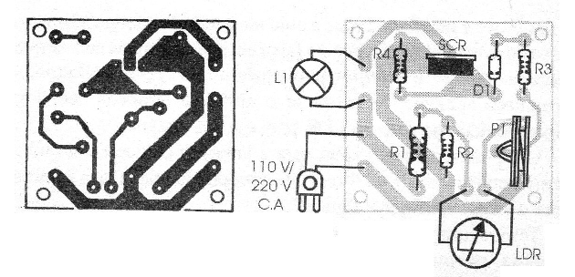
In Figure 3 we have the complete diagram of the apparatus, noting that the SCR can be the TIC106 or any of its series. The suffix must be B, if the network is 110 V and D, if the network is 220 V.
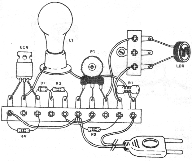
The assembly may be built on the basis of a terminal strip or printed circuit board. These elements are fixed inside the box.
The assembly on the terminal strip is shown in Figure 4 and the printed circuit board assembly in Figure 5.
For the LDR we use a 3-terminal bridge which allows its attachment to receive light through the hole in the housing.
In Figure 6 we show the way to execute its fixation. The box can be made of plastic or wood and its dimensions are not critical, since few are the components that will be in its interior.
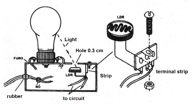
The LDR can be of any round type. For the power cable, a pass-through rubber should be used, thereby preventing a stronger accidental pull from damaging the inner circuit. Note the knot on the power cord.
The lamp is built in a conventional porcelain or plastic socket that is fixed to the housing by means of a central bolt with nut. This same bolt can be used to secure the terminal bridge with the components.
The resistors are all 1/8 W or larger except R1 which should be at least 1/2 W as it tends to a little heating when in operation.
The trimpot must be accessed by a small hole in the box or by its bottom to allow adjustment of the ideal operating point.
TEST AND USE
The test is immediate. Connect it to a power supply unit. By turning the trimpot shaft there must be a range which the lamp remains off. Adjust the trimpot on a table so that the lamp remains off. If when setting the light goes on, put your finger in the LDR hole to turn it off.
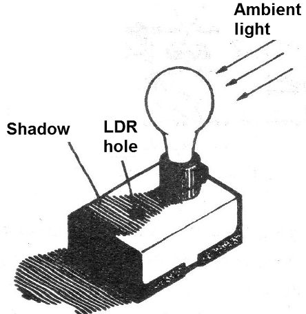
An ideal position for the lamp is where the ambient light is affected in such a way that the lamp itself shades over the LDR, see Figure 7.
We have a great adjustment when the lamp usually stays off and then, by lighting a match nearby (on the side of the LDR hole), it lights up and stays on.
Then, by shading using your hand over the LDR, the light goes out.
Having adjusted the lamp, do your demonstrations (or bets).
Explain to everyone that you get to turn the light bulb on with a match or lighter and turn it off with a blow or "suppressing" it.
Semiconductors:
SCR - TIC106B or D - Silicon Controlled Diode (SCR)
D1 - 1N4002 - silicon diode
Resistors: (of 5%)
R1 - 47 k x 1/2 W - yellow, violet, orange
R2 - 4.7 k x 1/8 W - yellow, violet, red
R3 - 1k x 1/8 W - brown, black, red
R4 - 10k x 1/8 W - brown, black, orange
P1 - 47 k - trimpot
Miscellaneous:
LDR - Photo-resistor (any round type)
L1 - 5 W at 100 W - common lamp of 110 V or 220 V
Printed circuit board or terminal bridge, assembly box, power cord, wires, welding, socket for the lamp, etc.


