When two sensors are activated almost at the same time, or two switches are pressed under the same conditions, it is difficult for an observer to know which one was the first. This condition can occur in both automation, control and alarm devices as well as in recreational devices, such as a set of reaction speed, as indicated in the introduction.
The design we are introducing allows us to know without a doubt which of two switches or sensors has been activated first.
In the original circuit, we will use indicator LEDs, but in its place power steps with relays, SCRs, Power FETs and other components can be used to control devices ranging from automatism to alarm systems.
The design is based on integrated low-cost CMOS technology and can be powered with voltages from 3 to 15 V. In standby condition the consumption is extremely low which allows it to be powered by batteries without problems.
CMOS Technology 4XXX
While there are today complex components such as microprocessors, microcontrollers, and DSPs which can be used to perform any function we need in automation and control work, the 4XXX family CMOS technology, of which 4011 is a representative, is still a preferred solution when we need simple things and this happens frequently. So we should not "kill a fly with a cannon" using very complex devices when we can do the same with ordinary low-cost integrated circuits that can be easily found. The CMOS 4XXX family of digital integrated circuits is an example of this. The great amount of functions it possesses allows its association or even individual use in a huge range of applications in which it is even better. This is why CMOS devices are still so popular among designers.
HOW IT WORKS
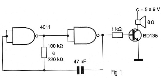
The basis of the design is the 4011 circuit consisting of 2 input NAND gates. Since we need 6 ports for the design and each 4011 integrated circuit has only 4, two of them will be needed. The two remaining ports of one of the built-in can be used in an audio oscillator if we want, besides the visual signal, an audio signal when one of the sensors is pressed.
A suggestion of an oscillator for this purpose by driving a piezoelectric transducer is shown in Figure 1.
We then have two Flip-Flops Set-Reset which are connected in such a way to each trigger a LED indicator.
When the RST switch is pressed for a moment the two flip-flops are reset and the LEDs on their outputs remain off.
Flip-flops are powered by two NAND gates connected so that when one receives a high input level and thus provides the trigger signal for the corresponding Flip-flop, it immediately disables the other Flip-Flop. This way, if the other Flip-Flop receives a firing signal a fraction of a second later, this signal "does not pass".
The signal for firing comes from the pressure switches or even reed-switches if we wish to trigger using magnets. Another possibility is to use resistive sensors or even logic circuits that are kept low, are active with the output going to the high level.
In the basic configuration, we have the activation of LEDs, but nothing prevents us from having other interfaces as explained in the introduction.
In Figure 2, we show some types of power interfaces that can be driven by this circuit.
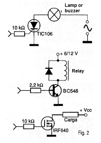
In the case of the relay interface, 6 or 12 V types may be used depending on the power supply, with coils requiring currents in the range of 20 to 100 mA for the drive.
In the case of SCRs, we remember that once they are triggered, they remain even after the circuit has been reset. There should be a separate reset for these components.
In all cases, where the interfaces must control high currents, the components must be built in heat radiators.
ASSEMBLY
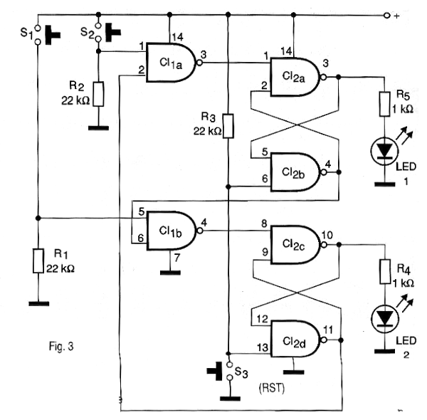
In Figure 3, we have the complete diagram of the device, without the power supply that can be external or formed by batteries (the consumption is of the order of 1 mA with the LEDs off).
The arrangement of the components on a printed circuit board is shown in Figure 4.
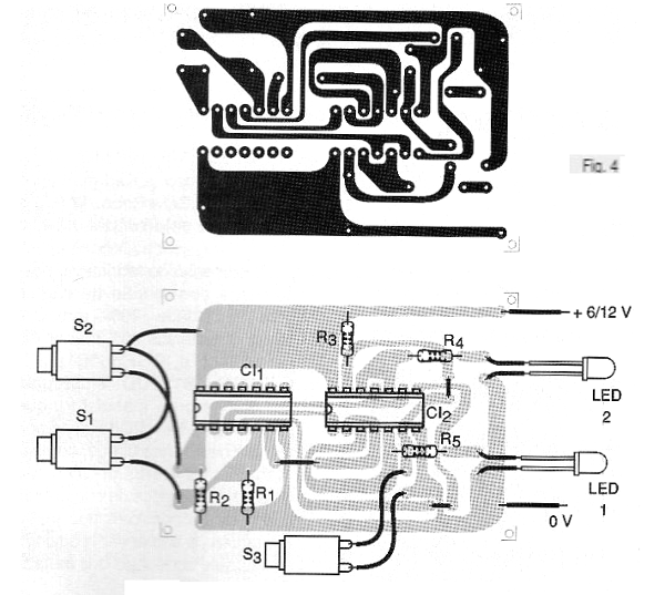
The wires for the sensors or drive switches can be very long (up to more than 10 meters).
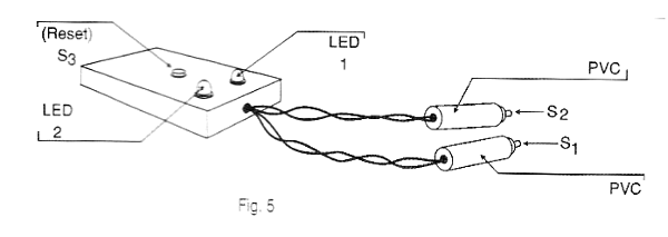
The LEDs are common red and green to differentiate which switch or sensor they match.
In a recreational application, such as a speed game, the set can be built in a plastic box as shown in Figure 5.
In Figure 6, we show the device being adapted for an application in the Experimental Physics laboratory, detecting which of two bodies arrives before the ground in a free fall experiment.
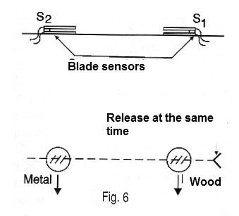
If resistive transducers are used, the 22 k ohms resistors in series can be replaced by adjustment triangles from 100 k to 1 M ohms according to the resistance of the sensor.
TEST AND USE
Testing the device is simple. Turn on the power. If one or both LEDs light up, press the S3 (RST) switch momentarily. Both LEDs should turn off.
Then, with the LEDs off, press switch S1. Only LED1 should light up. Press RST to delete it and now S2. Resetting again, try to press both at the same time. Only one of the LEDs should light up.
Proven its operation, the final installation may be made and it is ready to be used.
Semiconductors:
CI-1 - 4011 - Integrated Circuit CMOS
LED1, LED2 - Common LEDS (red and green)
Resistors: (1/8 W, 5%)
R1, R2, R3 - 22k ohms
R4, R5-1K ohms
Several:
S1, S2, S3 - Pressure switches NA
Printed circuit board, power supply or batteries, wires, solder, mounting box, etc.