This is not a simple blinker for the kind of effect we described in the introduction.
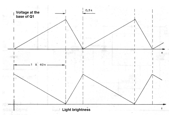
The lamp actually seems to dim until all of its light disappears, in a smooth process.
The circuit uses a Texas Instruments 8A triac as a base and a unijunction transistor trigger, in addition to a sawtooth oscillator with another unijunction.
The only adjustment which exists is the effect frequency that can vary from one cycle per second to one cycle every 30 or 40 seconds.
All components are small, so in the case of a lamp, nothing prevents all of them from being installed in the object's own base.
In case of higher power controls, as the triac tends to heat and needs to be mounted on a heat radiator, we recommend using a box with dimensions of at least 10 x 6 x 5cm.
In Figure 1, we give the waveform that illustrates the behavior of this circuit.

Its characteristics:
Maximum load: 800 watts (110 V) 1 600 watts (220 V)
Time range: 1 to 40 seconds
Supply voltages: 110 or 220 VAC
THE CIRCUIT
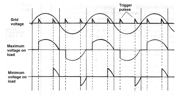
The period that occurs between the beginning of a half-cycle of the feed and the point at which the triac pulse is generated determines the power that is applied to the load (lamp).
If the pulse occurs with a small delay, the trigger occurs at the beginning of the half-cycle and the highest power is applied to the load.
In this case, this charge is the bulb that lights up at maximum brightness.
If the pulse is applied at the end of the half-cycle, less power is brought to the load and the lamp brightness is lower (Figure 2).

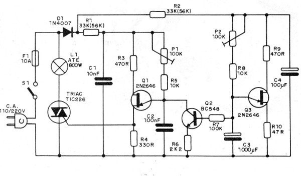
To control the triggering of the unijunction which generates these pulses, we use a second oscillator with another very slow unijunction (Q3).
As capacitor C3 charges through P2 and R8 the voltage at the emitter of transistor Q3 also rises and thereby the base voltage of Q2.
The voltage applied to the Q2 base directly controls the delay in the production of the triac clock by the unijunction transistor Q1.
When the base voltage of Q2 is low (start of charge of C3), the resistance represented by Q2 is high, so that the splitter formed by P1, R5, Q2 and R6 can apply a higher voltage in the capacitor C2 soon in the start the half-cycle and trigger Q1.
The pulse is produced at the beginning of the half-cycle and the lamp has its maximum brightness.
This maximum brightness is precisely adjusted by P1.
As the voltage in the capacitor C3 rises by its charge, the base voltage of Q2 increases, which gradually leads to a lower resistance.
As a result, the load of C2 that will reach the trigger voltage of Q1 is decreasing, closer to the end of the half-cycle.
The power applied to the load is then slowly reduced with the charge of C3 until the moment Q3 commutes.
When this occurs, suddenly the voltage at C3 drops almost to zero, and with it the base voltage of Q2.
Again, the clock starts to be produced at the beginning of the half-cycle with the light coming on and a new cycle starting.
P2 may be increased to give a longer cycle.
ASSEMBLY
In Figure 3, we have the complete diagram of our device.

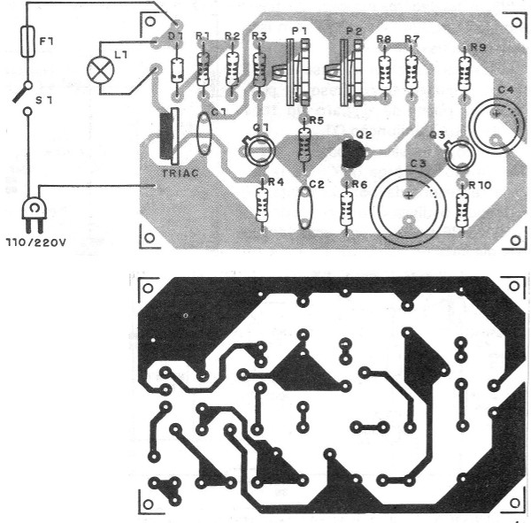
In Figure 4, we give the printed circuit board for the assembly.

The position of all polarized components, such as diode D1, unijunction transistors, triac and transistor Q2, must be strictly observed.
The values in parentheses for R1 and R2 correspond to the 220 V network.
In this voltage, it is also convenient to use for D1 o1N4007 or BY127.
P1 and P2 can either be trimpots or potentiometers, all depending on the need to change the behavior of the device with greater or less frequency.
C3 and C4 are electrolytic capacitors for 25 V or more and the resistors can be 1/8 or 1/4 W.
The triac must be equipped with a good heat radiator, especially if it has to work with maximum powers.
C1 and C2 are ceramic or polyester, with any voltage from 25 V.
TEST AND USE
To test the unit, place a lamp of 5 watts as load (L1), turn on the unit and set P1 to obtain the minimum brightness or approximately ? of the maximum brightness.
Then, set P2 to obtain cycles of brightness change at the desired frequency.
Then, adjust P1 again so that the brightness variation of the lamp occurs between the maximum and zero, with sudden lighting.
Once the operation is confirmed, it is only necessary to make the final installation, remembering that for high power loads the connection wires must be thick.
Triac - TIC226 for 200 V if your power grid 110 V or for 400 V if your power grid is 220 V
Q1, Q3 - 2N2646 - unijunction transistors
Q2 - BC548 or equivalent - general purpose NPN transistor
D1 - 1N4004 or 1N4007 - silicon diode
L1 - lamp up to 800 watts in the 110 V network and up to 1600 watts in the
220 V
P1, P2 - 100k - trimpots or potentiometers
F1 - 10 A fuse
S1 - single switch
R1, R2 - 33 k x 1 W - resistors (orange, orange, orange) for the 110 V or 56 k x 1 W - resistors (green, blue, orange) for 220V network
R3, R9 - 470 ohms x 1/8 W - resistors (yellow, violet, brown)
R4 - 330 ohms x 1/8 W - resistor (orange, orange, brown)
R5, R8 - 10k x 1/8 W - resistors (brown, black, orange)
R6 - 2k2 x 1/8 W - resistor (red, red, red)
R7 - 100k x 1/8 W - resistor (brown, black, yellow)
R9 - 470 ohms x 1/8 W - resistor (yellow, violet, brown)
Cl - 10 nF - ceramic capacitor
C2 - 100 nF - ceramic or polyester capacitor
C3 - 1000 uF x 25 V - electrolytic capacitor
C4 - 100 uF x 25 V - Electrolytic capacitor
Miscellaneous: printed circuit board, mounting box, power cable, fuse holder, heat radiator for triac, socket for controlled lamp or lamps, knobs for potentiometers, wires, welding etc.


