Not a few people take their portable radios, Walkman and other small electronic devices to bed, and sleep with their power on.
The result is the complete wear of the batteries which is not very interesting considering the current cost.
What we propose in this article is an interesting solution to this problem, since it solves the question as much of the cost of the batteries that are eliminated as of the fact of sleeping with him on providing a timing.
We present a battery eliminator, that is, a source that replaces the batteries of your device and that automatically shuts off after a set time.
If we want more time, just press a button and we will have a new timing.
The basic version of this design is for devices powered by 4 batteries (6 volts) from small to large, but changes can be made to power other types of appliances.
If the powered device has an eliminator input no changes need to be made in your circuit.
If it does not, adaptation is relatively simple.
CHARACTERISTICS
Input voltage: 110/220 VAC
Output voltage: 6 V (modifiable)
Maximum output current: 500 mA
Timing: 1 minute to 30 minutes
HOW IT WORKS:
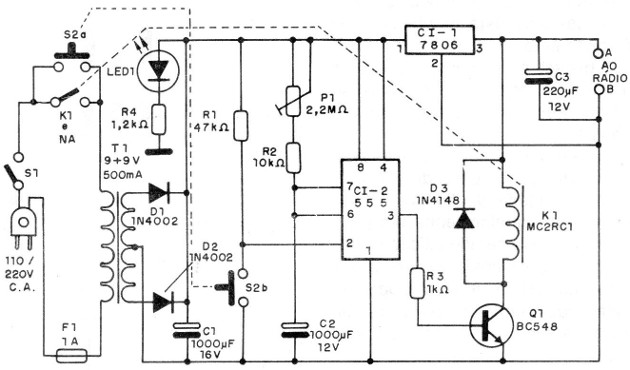
The circuit basically consists of a stabilized power supply where the transformer T1 lowers the mains voltage which is then rectified by the diodes D1 and D2.
The filtering is done by the capacitor C1 and the regulation through an integrated circuit 7806, which provides at its output 6 V.
We can use the 7805 to get 5 V or the 7812 if we want 12 V.
In this case, 12 V, however, you will need to use a secondary 12 V transformer.
This source also powers the timing circuit.
In this way, when we press S2 (double pressure switch) for a moment, we supply power to the circuit and at the same time we take the firing pin 2 from a monostable 555 to the low level, which causes the trip.
This trip leads the output of the integrated circuit to high level which polarizes the transistor in order to energize the coil of the relay.
The closing of the relay returns the circuit keeping its power even if we release S2.
The closing time of the relay and therefore the supply of the circuit with the 6 V output will be given by the potentiometer P1 and the capacitor C2.
With the potentiometer P1 of 2.2 M ohms and the capacitor C1 of 1 000 uF we have approximately 30 minutes of timing, neglecting the tolerances of the components.
This means that after 30 minutes of firing S2, the Cl-1 output goes back to the low level which brings the transistor to the cut.
The relay is de-energized by opening your contacts. As a result, the power supply to the circuit is completely cut off with its total shutdown.
For a new timing, just press S2 for a moment.
Even during a timing cycle, if S2 is pressed we will have a new time count.
Greater timing is possible provided that capacitors of excellent quality are used since leaks can lead the circuit to non-tripping.
ASSEMBLY
In figure 1 we have the complete diagram of the timed battery eliminator.
The arrangement of the main components on a printed circuit board is shown in figure 2.
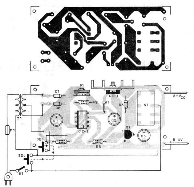
A small heat radiator should be attached to the integrated circuit 7806 (Cl-1) if necessary, ie if excessive heating occurs on the Cl.
For CI-2 we suggest the use of an 8-pin DIL socket.
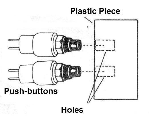
If the reader has difficulty in obtaining a double pressure switch, you can improvise one with two single switches mounted side by side with a single button holding them as shown in figure 3.
The relay is of the type used for mounting on printed circuit board and a DIL socket can be used.
However, lower cost equivalent relays can also be used.
The electrolytic capacitors are for 12 V or more and the resistors are 1/8 or 1/4 W with 5 to 20% tolerance.
The rectifier diodes admit equivalents and D3 is any commonly used silicon diode.
For the transistor we can use equivalents like the BC547 or even BC549. Switch S1 is optional, serving to interrupt the timing by switching off the appliance, as well as the LED1 in series with the R4 resistor, whose function is to indicate that the appliance is monitored, in operation.
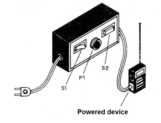
The fuse is mounted on a suitable holder and the whole assembly can be mounted in a plastic housing as in figure 4.
In figure 5 we have the way to do the adaptation in a radio.
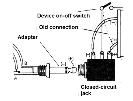
Note that the polarity of the input wire, if your device has an adapter jack, must be identified.
Some devices have a positive pole on the outside of the plug while others have an internal pole.
Check before turning on your own, as reversing may cause damage to the powered device.
PROOF AND USE
Once the installation is complete, connect a 6 V lamp or a multimeter on the DC voltage scale to read 6 V.
Press S2 with the potentiometer in the shortest time position. The output voltage should go to 6 V for a time interval of a few minutes. After that there is a small snap of the relay that opens its contacts and the voltage drops to zero.
Once the operation is confirmed, it is only necessary to test the power supply by setting P1 the desired time for the shutdown.
We can adapt this unit to function as a timer for other types of load using the other contact available in the relay for this purpose.
Simply pull for this purpose wires up a pair of insulated terminals. In figure 6 we show how to make a more complete adaptation with power.
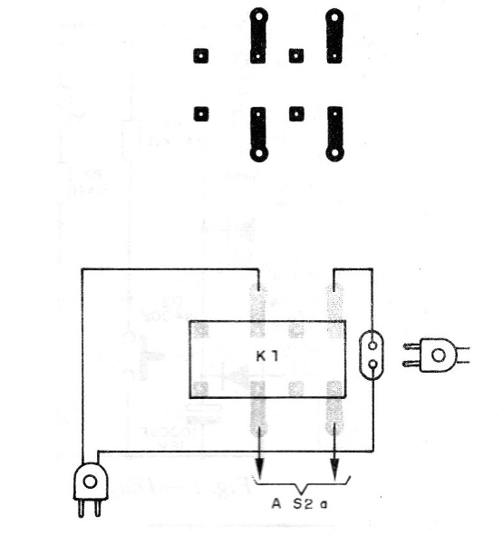
Remember that the current capacity of the relay used is 2 A which means 200 W in the 110 V network and 400 W in the 220 V network.
To use the unit just press S2 after turning on S1 and use the radio, walkman or other power. At the end of the time, if you want to hear more music just press S2 again.
CI-1 - 7806 - integrated circuit voltage regulator
CI-2 - 555 - integrated circuit timer
Q1 - BC548 - NPN general purpose transistor
D1 and D2 - 1N4002 or equivalent silicon diodes
D3 - 1N4148 - silicon diode of general use
K1 - 6 V relay
S 1 –On-off switch
S2 - double push-button
F1 - 1A - fuse
T1 - transformer with primary according to the local grid and secondary of 9 + 9 V x 500 mA.
C1- 1000 uF x 16 V - electrolytic capacitor
C2 - 1000 uF x 12 V - electrolytic capacitor
C3 - 220 uF x 12 V - electrolytic capacitor
P1 - 2.2 M ohms - potentiometer
R1 - 47 k ohms x 1/8 W - resistor (yellow, violet, orange)
R2 - 10 k ohms x 1/8 W - resistor (brown, black, orange)
R3 - 1k ohms x 1/8 W - resistor (brown, black, red)
R4 - 1.2 k ohms x 1/8 W - resistor (brown, red, red)
Miscellaneous: Printed circuit board, mounting box, fuse holder, power cord, potentiometer knob, connector for powered equipment, wires, solder, etc.


