This article originally was part of one of our spy books of the 80's and has been updated to a current edition (2015).
In our version we will describe the trip by means of a reed-switch and in a timed manner. Although the discharge has more than 2 000 Volts, because we use a car ignition coil, as the current is very low, there is no danger of electrocution.
The shock, of the same intensity, is very reminiscent of that accidentally taken in car ignition systems. (If the reader wants to experiment before assembling, knows how to find an equals!).
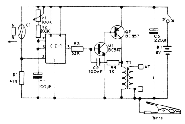
In figure 1 we have the complete circuit of the portable electrification system that is fed by common alkaline batteries, for greater autonomy.

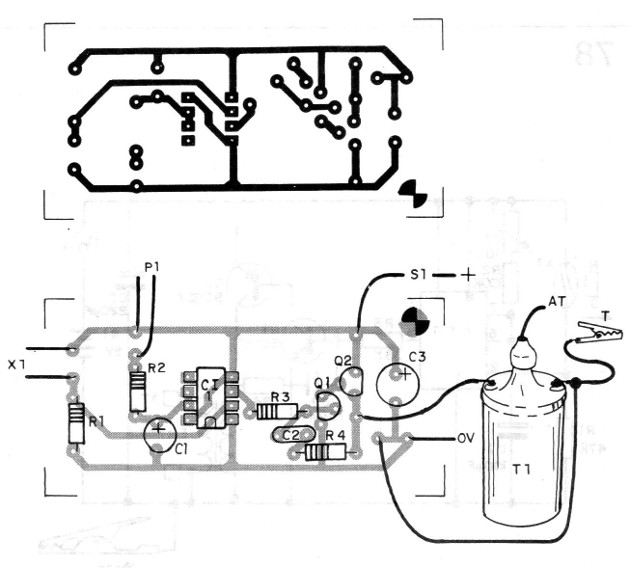
In figure 2 we have the arrangement of the components on a printed circuit board.

The coil and ignition of car or even motorcycle of any kind, and the power transistor must be mounted on a heat radiator. P1 sets the frequency of the signal to the inverter and must be adjusted in order to obtain the best output or higher discharge voltage:
The timing of the shock is only a few seconds, repeating if the object is not replaced in order to increase the life of the power supply, ie the durability of the batteries.
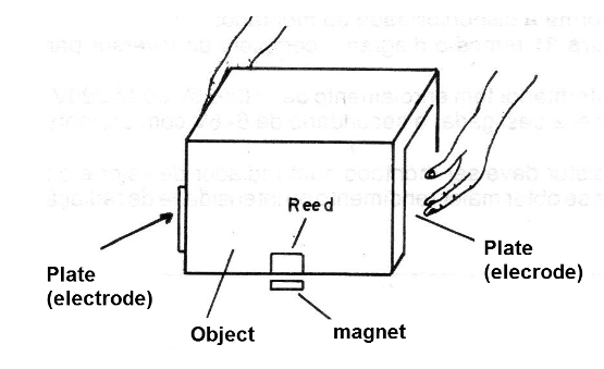
The assembly can be installed in a plastic housing and for use one of the outputs must be grounded or the two electrode system to be used simultaneously, as shown in Figure 3.

Portable use can be made by using a grounding claw that will be attached to any large metal object that exists nearby.
The reed-switch and the magnet are positioned so that the object's withdrawal of position causes its actuation.
SEMICONDUCTORS
Cl-1 - 555 - integrated circuit
Q1 - BC547 - NPN general purpose transistor
Q2 - BC557 - general purpose PNP transistor
RESISTORS
R1 - 47 k - resistor (yellow, violet, orange)
R2 - 100k - resistor (brown, black, yellow)
R3 - 33 k - resistor (orange, orange, orange)
P1 - 100 k - potentiometer or trimpot
R4 - 1 k - resistor (brown, black, red)
CAPACITORS
C1 - 100 uF - electrolytic capacitor
C2 - 100 nF - ceramic or polyester capacitor
C3 - 220 uF - electrolytic capacitor
SEVERAL
X1 - Reed-switch
S1 - Single switch
B1 - 6 V - 4 medium alkaline batteries
X2 - Ignition coil - see text
Printed circuit board, mounting box, battery holder, wires, alligator clips, solder, etc.