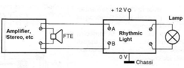
The circuit we present produces a very interesting visual effect in the car or from home stereo equipment: it makes one or more lamps blink to the rhythm of the music played. see that what differs from this circuit of conventional panel is that instead of weak LEDs it operates with lamps, including those inside the car itself (courtesy) if the reader wishes.
The setup used is quite simple and can operate directly from the audio output of any sound equipment. It is connected directly to the outputs of the speakers and if we want a stereo effect just mount two equal units.
The reader can either use standard white bulbs or, if you prefer, colored bulbs.
Characteristics:
* Power supply voltage: 12 volts or more
* Maximum output current: 3 amps
* Lamp voltage: 6 or 12 volts (see text)
* Minimum audio power for excitation: 50 mW
HOW IT WORKS
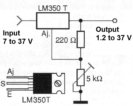
The basis of the design is an integrated LM350T circuit consisting of an integrated voltage regulator for 3 amps.
The voltage that this component provides at its output depends on the voltage applied at its reference or setpoint (AJ). In normal applications, a voltage divider formed by a trimpot and a resistor, as shown in figure 1, set the output voltage that will be between 1.2 Volts minimum to 2 or 3 volts below the maximum input voltage that is 37 volts.
However, as this integrated circuit is very sensitive, with small power, we can modulate the output voltage and therefore the voltage applied to a set of lamps using a single transistor (Q1).
With the transistor in the cut (open) the output voltage is maximum and the lamps light up at maximum brightness. With the transistor saturated, the voltage drops to near 1.2 Volts and the lamps virtually extinguish.
To produce voltage changes according to the music of a stereo the base of the transistor is connected to a circuit composed of a capacitor, two resistors, a diode, a potentiometer and a transformer.
The Rx resistor limits the power applied to the circuit, its value being a function of the power of the sound equipment, or the volume at which it is used. An approximate table is given below:
| Power per channel | Rx value |
| (watts) | (ohms x watts) |
| 0 to 2 | 10 ohms x 1/2 W |
| 2 to 5 | 22 ohms x 1/2 W |
| 5 to 20 | 47 ohms x 1/2 W |
| 20 to 50 | 100 ohms x 1 W |
| over 50 | 220 ohms x 1 W |
It is important to note that many sound equipment indicates power that does not really match the actual value. Thus, it is common to have devices that "say" themselves with more than 50 watts per channel, and that in fact do not provide real powers of more than 10 watts and even less.
In this case, using a resistor according to the power indicated on the apparatus the reader will notice a certain difficulty in the excitation of the lamps showing that the equipment is indicating a false output power. In this case the value of Rx must be reduced.
The audio signal then passes through a transformer whose purpose is to adapt the impedance of the sound output circuit to the input of the transistor. In the design we used a common power transformer that is usually equipped with a high impedance (10 V or 220 V) and a low (5 to 12 V) winding.
The signal from the transformer switches to the sensitivity setting potentiometer. This potentiometer allows adjusting the effect according to the volume we use for the sound equipment.
The next step in the signal path is to pass via R1 to a rectifier diode and a capacitor (C2). The signal, which is now continuous, excites the transistor and the capacitor provides some inertia to the effect. This inertia is important for this purpose, preventing the bulbs from flashing too fast. Choosing the appropriate value of this component depends on experience. Try values between 1 and 100 uF.
The transistor is then excited by controlling the LM350T integrated circuit in the way we have already explained.
It is important to note that there is a voltage drop of the order of 2 to 3 volts in the integrated circuit. If we use 12-volt bulbs they will receive 2 to 3 volts less than normal, which will reflect in the final brightness.
To avoid this problem we indicate the use of 6-volt lamps, so that we can set the integrated output to P2 at this value when there is maximum excitation. Another possibility is to use more than 12 volts at the input and adjust P2 so that the voltage in the 12 volt lamps is correct.
200 mA lamps provide good brightness when used on this unit but the choice of the type used depends on the player.
ASSEMBLY
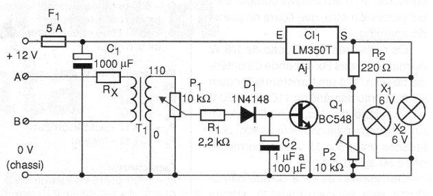
In figure 2 we show the complete diagram of the apparatus.
The assembly makes use of a printed circuit board which is shown in figure 3.
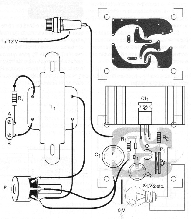
The integrated circuit must have a heat radiator, especially if the lamps being supplied are of greater consumption. P2 is a common trimpot and P2 is a potentiometer that will remain on the instrument panel.
The R1 and R2 resistors are 1/8 W or larger but Rx depends on the sound power. T1 is a transformer with primary winding of 110 V or 220 V and single or even double secondary (one of the terminals will not be used) with voltages between 5 and 15 volts and currents between 50 and 500 mA.
The capacitors C1 and C2 are electrolytic for 16 V or more. D1 supports equivalents.
The input protection fuse is important and must be installed in proper bracket.
TEST AND USE
Initially, without the bulbs connect the instrument to a 12 V source and output a multimeter on the voltage scale to measure 12 volts, as shown in figure 4.
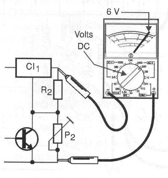
Without connecting A and B to anything, set P2 to have a voltage of 6 volts or according to the lamp used if the input voltage is higher.
Then remove the Meter, do not disturb P2 again, and turn the bulbs on as a load (at the output).
Now, connect A and B to the output of any stereo, as shown in figure 5.
Set the unit to low volume (1/4 or 1/3 of maximum volume) and set P1 so that the lamps blink to the rhythm of the music. If you can not adjust, reduce Rx.
Change C2 if you want more or less inertia in the drive.
Once the operation is confirmed, install the unit in a box and then in the car or by your sound. For domestic use, mount a 12-volt or 15-volt supply with 3 A and power the unit.
Whenever you change the volume of your stereo, set the sensitivity to P1.
Semiconductors:
CI-1 - LM360T - integrated circuit, voltage regulator
Q1 - BC548 or equivalent - general purpose NPN transistor
D1 - 1N4148 or equivalent - general purpose diode
Resistors: (1/8 W, 5%)
Rx - see text
R1 - 2.2 k ohms
R2 - 10 k ohms
P1 - 10 k ohms - potentiometer
P2 - 10 k ohms - trimpot
Capacitors:
C1 - 1000 uF / 16 V - electrolytic
C2 - 1 uF at 100 uF / 16 V – electrolytic
Several:
X1, X2 - 6 to 12 V lamps - see text
T1 - Transformer with primary 110/220 V and secondary from 5 to 12 V with current from 50 to 500 mA - see text
F1 - 5 A fuse
Printed circuit board, heat radiator for integrated circuit, fuse holder, lamp sockets, mounting box, potentiometer knob, wires, solder, etc.