
This is accomplished by connecting the two amplifiers to the same load, but each applying the same signal with inverted phase, as shown in Figure 1.
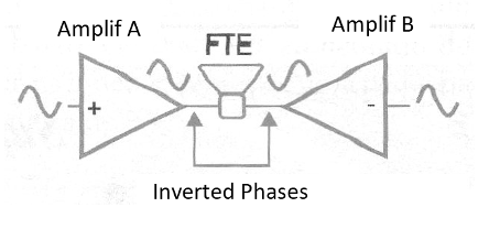
Common amplifiers that do not have a coupling capacitor to the speaker can be connected in this configuration, as long as the signals applied to their inputs have inverted phases.
This can be achieved with an amplifier circuit as shown in Figure 2.
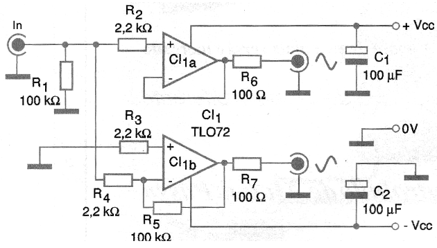
This adapter circuit uses two operational amplifiers of the same TL072 or equivalent circuit.
The power supply should be symmetrical from 6 to 12 V and as the consumption is extremely low the assembler has two options: get the power from the circuit itself with which the adapter will work or use two batteries.
Typically many audio preamplifiers use symmetrical sources which can be harnessed to power this circuit.
The input signal should have an amplitude of approximately 1 Vrms. It is important to check if there are no offset voltages at the outputs, ie, presence of voltage when there is no input signal. The typical value for this voltage should be less than 5 mV.
To reduce the noise level in the circuit it is convenient to use metallic film resistors.
CI-1 - TL072 - Dual Operational Amplifier
R1, R4, R5 - 100 k ohms x 1/8 W - resistors
R2, R3 - 2.2 k ohms x 1/8 W - resistors
R6, R7 - 100 ohms x 1/8 W - resistor
C1, C2 - 100 uF x 16 V - electrolytic capacitors
Miscellaneous:
Printed circuit board, shielded metal box or mounting hardware inside amplifiers, wires, welding, input jack, output jacks (optional), etc.


