

Obs. The circuit originally was published in a Brazilian magazine and translated into English to be part of my book Electronic Projects from the Next Dimension (2001).
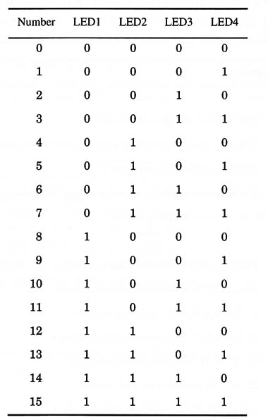
The numbers are given by four LEDs, each of which can represent 0 (off) and 1 (on). They can be on or off in any combination as shown in the table.
When you press S, the LEDs will flash to produce random combinations.
When S is released, the LEDs will remain in one of the combinations correspondent to the generated number. Unlike the previous project, this circuit does not have an “inertia” circuit that causes a delay in arriving at the generated number.
Paranormal Experiments
The subject must guess what number will be generated. As suggested in the previous project, there are several ways to improve the tests. The LEDs can be associated with combined elements such as number and color, or a table with 16 different symbols can be created.
As in the previous project, the subject can perform PK experiments by trying to set the generated number using his mental powers. See the next project for more suggestions about experiments of this type.
In transcendental meditation and biofeedback, the LEDs running in many combinations can help the subject to reach the necessary mental states to make experiments in this area. The speed of the LEDs can be reduced, as indicated in the “Suggestions” section, to help the experimenter if appropriate.
For radiesthesia experiments, the influence of a pendulum on the results can be tested.
UFOs and ghosts: How can ghosts be detected by a generated number? Can the presence of paranormal phenomena in a particular location influence the numbers generated by this circuit? You can experiment to find out.
How It Works
Two of the four NAND gates of a TTL IC 7400 are used as an oscillator whose frequency is determined by R1 and C1. This circuit applies its signal to a third NAND gate, controlled by S1 in a manner such that pulses pass through it only if S1 is pressed. This means that, when pressing S1, the pulses generated by the oscillator are applied to the second block of the circuit, formed by IC2.
IC2 is a divider by 2 and divider by 8 in a single chip. This means that it is a binary divider that can count up to 16 and give the results in four outputs, Q1, Q2, Q3, and Q4.
To each output is connected an LED that indicates its state. The LED will glow when the output is high, representing a 1, and will remain off if the output logic level is a 0.
As with all TTL circuits, the power supply voltage must be 5.0 V. In practice, the circuit will function with any voltage between 4.5 and 5.5 V. This means that four AA cells are not a suitable power supply for this circuit. To power the circuit from AA cells, we have to add two common diodes in series with them as shown in Fig. 1.

Each diode will produce a voltage drop of about 0.6 V in the power supply voltage, reducing the total voltage applied to the circuit to 4.8 V. This is a suitable value for its operation.
You can also power the circuit using the power supply shown in Fig. 2.

The input transformer has a primary winding rated for the ac power line (117 Vac), a secondary winding of 7.5 to 9.0 V, and currents in the range between 50 and 300 mA.
The diodes have a voltage rating of 12 V or more. It is not necessary to place the IC 7805 on a heatsink, as the circuit drains a very low current.
Assembly
Figure 3 shows the complete diagram of the binary random number generator.
The components can be placed on a small printed circuit board as shown in Fig. 4.

Observe the position of the polarized components, such as the LEDs. If they are reversed, the circuit will not function properly. The LEDs can be mounted with long terminals to allow them to pass through holes in the panel as described in the previous project.
The circuit can be installed in a plastic or wooden box. The size will depend in the battery holder format and size or if the assembler intends to use a power supply with a transformer.
The panel can be designed to use cardboard panels with symbols as described in article ART083E
Testing and Using the Circuit
Place the cells in the cell holder and press S1. The LEDs will flash at a fast rate. In some cases, you will have the sensation that the LED connected to Q1 and Q2 glows with low brightness because of its flash speed.
When you release S1, the LEDs will stop in one of the combinations shown in the table. Try it a few more times to make sure the next combination isn’t the same. If the circuit doesn’t run, try using one diode instead of two in the power supply (if powered by cells).
Using the Circuit
The experiments for this device are the same as described in ART083E
Suggestions
- You can make the LEDs run faster by reducing the value of C1. Values between 0.01 and 0.044 µF can be used.
You can add inertia to the circuit to make the LEDs run for a few seconds after S1 is released. This is accomplished by installing a 100 to 470 µF capacitor in parallel with S1.
Semiconductors
IC1 - 7400 TTL IC, four two-input NAN D gates
IC2 - 7493 TTL IC, dual flip-flop
LEDs 1- 4 - Common red LEDs
Resistors
R1- 220 Ω, 1/8 W, 5% - red, red, brown
R2 - R5 330 Ω, 1/8 W, 5% - orange, orange, Brown
Capacitors
C1 - 0.1 µF, ceramic or metal film
C2 - 100 µF/6 WVDC, electrolytic
Miscellaneous
S1 - Pushbutton, normally open
B1 - Four AA cells + two diodes (1N4148) or a 5 V power supply
Printed circuit board, plastic or wooden box, Wires, battery holder, solder, etc.


