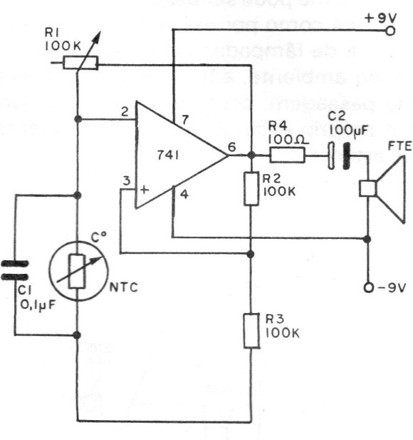
We can then have a circuit that triggers an alarm when the temperature of the sensor exceeds a certain value that will be set by the trimpot setting conditions. NTCs are common components, so the reader will have no difficulties obtaining them, but we must remember that there are well-defined limits for the maximum temperatures that they can be subjected to, which means that the operation of this device should only be done in the range temperature between -20 °C and 80 °C.
The complete circuit of the alarm is then shown in figure 1 and either of the two indicated for the assembly described in ART2670 are used as power supplies.

The used NTC can be of any type that has a resistance between 10 k and 100 k in the temperature of 20 ºC. The differences existing from one type to another can easily be compensated by the adjustment of the trimpot.
Once the circuit is assembled, simply adjust the trimpot to the point where the unit does not swing. Warming up, even with NTC hands, the alarm should sound.
If the reader wants to use a common potentiometer instead of the trimpot and make a calibrated panel in terms of the trigger temperature for the device.
CI - 741 or any of its equivalents
R1 - 100k - trimpot
R2, R3 - 100k x 1/8 W - resistors (brown, black, yellow)
R4 - 100 ohms x 1/4 W- resistor (brown, black, brown)
C1 - 0.1 uF - polyester capacitor
C2 - 100 .uF x 16 V - electrolytic capacitor
NTC - common NTC from 10 k to 100 k
FTE - 8-ohm speaker
Miscellaneous: printed circuit board, symmetrical power supply, wires, solder, etc.


