

A hidden switch will make the bird sing whenever you want. The sound produced is loud, even with only two batteries.
With four batteries the volume increases, but if the reader really wants a very loud bird, just plug it into an amplifier. An interesting feature of this circuit is its simplicity, since only one transistor in a single oscillator does it all.
OPERATION
The oscillator used is a Hartley type with a transistor, where the inductance of the primary winding of T1, along with C3, determines the pitch of the corner.
C3 can be reduced if the reader wants a sharper corner, and in many cases, depending on the transformer used, one must experiment with changing this component to obtain the ideal corner. The corner oscillations that characterize the bird (Canary) are produced by connecting an RC network formed by R3 and C2 at the base of the transistor.
The value of C2 determines the frequency of these oscillations, and can also be modified if the reader does not like the effects very much.
The capacitor C4 functions as an "energy reservoir", where a charge becomes available after we release switch S1.
Thus, by pressing S1, the bird begins to sing and releasing S1, it does not stop immediately, but gives a variation of tone before the sound is muted and muted.The only adjustment that exists in the circuit is the point of oscillation and timbre that is made in trimpot P1.
The used speaker should be 8 ohm to match the transformer output.
In figure 1 we have the complete circuit of the bird.

In figure 2 we have the terminal strip version.

Figure 3 shows the printed circuit board version.
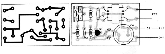
The main precautions that must be taken during assembly are:
a) Observe the position of the transistor in its placement, paying attention to the side that must remain its flat part. Be quick in welding this component.
b) The output transformer can be of any type for transistors, but it is convenient to have this component in hand before making the board, since the types available vary greatly in size. Be careful not to reverse your call.
c) When soldering the capacitors C2 and C4, the reader must observe, in addition to their values, the polarity, that is, the (+) or (-) marking in its enclosure.
d) For other capacitors, C1 and C3, care must be taken that the heat in the welding does not damage them.
e) The resistors have the values given by the colored bands. Observe them carefully according to the material list.
f) The trimpot must be carefully inserted into the plate; in the bridge its terminals must be slightly open to fit the welding points.
g) If your assembly is bridged, make the interconnections between the various points, using common pieces of wire.
h) Complete the assembly with the speaker, switch, and battery holder connection. For the latter, be aware of its polarity, which must be followed. The red wire of the holder corresponds to the positive pole.
PROOF AND USE
After all, check all the connections and, if everything is in order, put the batteries in the holder. Press S1 and at the same time set P1 to change the pitch and frequency of the oscillator. Depending on the setting, the bird's song will change its tone.
If the bird does not sing, start by checking the position of the transistor and the speaker connection.
If the bird still does not sing, the problem may be in the transformer.
Replace it with another of different characteristics.
Modifications in the chime of the corner can be made by changing the capacitors C1, C2 and C3. C1 and C3 make the corner sharper, while the reduction of C2 increases the speed of the pitch variations.
Q1 - BC548 or equivalent - NPN transistor
T1 - output transistor for transistors, with 500 to 1 k of primary impedance and 8 ohms of secondary
P1 - 100 k - trimpot
R1 - 1k2 x 1/8 W - resistor (brown, red, red)
R2 - 10k x 1/8 W - resistor (brown, black, orange)
R3 - 820 R x 1/8 W - resistor (gray, red, brown)
C1 - 22 nF - ceramic or polyester capacitor
C2 - 220 uF x 6 V or more ~ electrolytic capacitor
C3 - 100 nF - ceramic or polyester capacitor
C4 - 1000 uF x 6 V or more - electrolytic capacitor
S1 – push button
B1 - 3 or 6 V (2 or 4 small batteries)
FTE - 8 ohm speaker x 5 or 10 cm
Several. support for 2 or 4 batteries, terminal strip or printed circuit board, wires, solder, etc.


