

We describe the assembly of a 3-digit TTL counter module employing 7-segment displays of common anode. The module can be used as part of various types of projects such as object counters, people counters, frequency meters, wavelength meters and many other digital instruments. The circuit can be adapted to be used as a shield for microcontrollers.
The configuration is most common with the use of the well-known 7490 decade counters and 7447 7-segment decoders.
There is not much to do in terms of modifications or studies for immediate application: just power the circuit with 5 volts and apply the counting pulses at the input.
HOW IT WORKS
Each digit is commanded by a 7490 type counter which is programmed to count to 10 and which provides BCD outputs on pins 11, 8, 9 and 12. Pins 2 and 3 of the 7490 are the reset inputs that must be brought to high level to reset the count.
The BCD signals of the 7490 are fed to the decoders 7447 which provide at their outputs low voltage levels for the excitation of the segments corresponding to each digit to be displayed.
7-segment displays must have current limiting resistors in each segment. For TTL circuits these resistors are usually standardized at 220 ohm or 330 ohm. Smaller values provide greater brightness.
The consumption of each digit depends on the number of lit segments being around 100 mA for the maximum (turning on digit 8). This fact must be predicted in the calculation of the components of the source that surely must feed the rest of the circuit with which the meter will work.
It is important to note that this circuit has no latch which may be required in some applications, for example in instruments that operate by sampling. The latch consists of the circuit that retains the data of a counting process by displaying them on the display until a subsequent counting cycle is completed.
ASSEMBLY
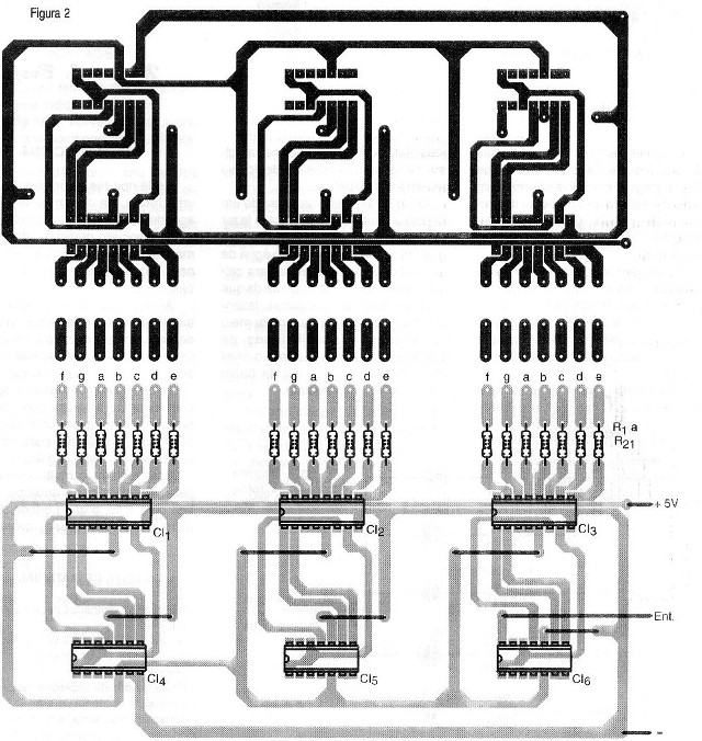
In figure 1 we have the complete diagram of the 3-digit counter module.

Displays can be on a separate board that would make it easier to attach to the instrument panel. For this purpose you can use a ribbon-type flexible cable (such as a computer printer) to make your connection. The display board depends on the type used. As there are many possible pinouts and sizes for these components we leave the design of this board for the reader itself.
The power supply must be that of the equipment being designed.
Remember that the 7490 changes state (count) with the negative transitions of the input signal, that is, when switching from the high level to the low of the input signal.
USE
It is up to each reader to use this circuit. Another important point that should be taken in its application is the maximum counting speed which for the common types (standard or normal series) is 18 MHz. For higher speeds, devices of other series such as LS must be used.
Semiconductors:
DY1 to DY-3 - 7-segment displays of common anode
CI-1 to CI-3 - 7447 - 7 segment BCD decoder TTL
CI-4 to CI-6 - 7490 - TTL decade counter
Several:
R1 to R21 - 220 ohm x 1/8 W - resistors
Printed circuit board, wires, solder, etc.


