Utilities:
• Determination of the noise level in a factory or other location where noisy machines and electronic devices operate.
• Assessment of the level of interference in locations where sensitive equipment or even household appliances subject to interference are to be installed.
• Determination of the intensity of noise produced by an industrial machine or a circuit.
• Survey of the noise spectrum of a site or produced by a machine with the help of the spectrum analyzer.
Constructive Details:
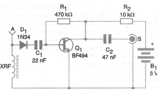
The circuit consists of an aperiodic radio receiver, that is, without tuning, capable of covering a frequency range that goes from a few tens of kilohertz to more than 5 Megahertz. We can connect it directly to an audio amplifier to hear these signals, connect it to a sensitive indicator instrument (AC voltmeter) or to the input of a spectrum analyzer.
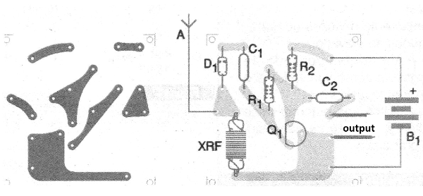
The printed circuit board is shown in Figure 2. The RF shock is formed by 400 turns of fine enameled wire (30 or 32 AWG) in a ferrite rod of 0.5 to 1 cm in diameter and up to 10 cm in length.
The consumption of the circuit is very low, and for greater sensitivity a germanium diode must be used. The antenna, which is optional, is telescopic type up to 1 m in length.

Semiconductors:
Q1 - BF494 or equivalent - RF transistor
D1 - 1N34 or equivalent - any germanium diode
Resistors: (1/8 W, 5%)
R1 - 470 k ohm
R2 - 10 k ohm
Capacitors:
C1 - 22 nF - ceramic
C2-47 nF - ceramic
Several:
B1 - 3V - 2 small batteries
XRF1 - View text
A - telescopic antenna
Printed circuit board, battery holder, output cable, printed circuit board, wires, solder.


