Powerful audio oscillators shape the last link in any alarm or warning system. However, good circuits which deliver high volumes are not always simple and therefore expensive. Just using a transformer for the circuit power, already represents a high expense for the assembly.
What we propose here is a different circuit, but of good power, which is characterized by the simplicity and no need for a power transformer. The circuit is powered directly by the 110 V or 220 V network, providing a good intensity audio tone to a speaker with minimum components.
Several similar units can be assembled and spread out where the audible warning should be required.
THE CIRCUIT
The base of the circuit is a relaxation oscillator with SCR. This configuration works as follows: after the rectification by D1, we obtain a direct voltage which, through R1, charges the capacitor C2. In parallel with C2, we have an SCR and a speaker, plus a neon lamp connected to the SCR gate.
With the charge of C2, the voltage between its armatures gradually rises until it reaches the lamp ionization value. For common neon lamp types this will be 80 V and it still stays lit, new switching occurs. The lamp goes out and then the SCR stops driving. A new cycle then begins.
In Figure 1, we have approximately the generated waveform, which is directly applied to the speaker.
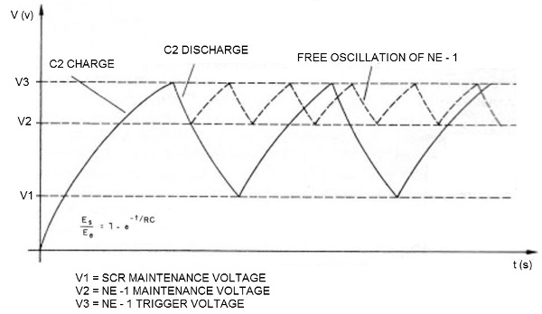
Note, then, that the frequency of this signal is given fundamentally by the time constant R1/C2. With the values indicated on the circuit, we will have a tone close to 500 Hz.
However, the sound power depends on the load of C2. If we multiply the load in Joules by the frequency, we have approximately the power.
For a 470 nF capacitor, which charges at a voltage of approximately 100 V until the triggering at a frequency of 500 Hz, we have:
Stored energy
E = ½ x C x V2
At where:
E = energy in Joules
C = capacitance in Farads
V = voltage in Volt
Then,
E = 1/2 x 470 x 10-9 x1002
E = 2.35 x 10⁻³
E = 2.305 mJ
Power
P = 2.35 x 10-3 x 500
P = 1,175W
At where:
P = power in watt
E = energy in Joules
f = frequency in Hertz
With a good performance speaker, this represents a reasonable volume.
Using a 2.2 uF capacitor for C2 and reducing R1 to 1 k, we will have about 5 W of power!
ASSEMBLY
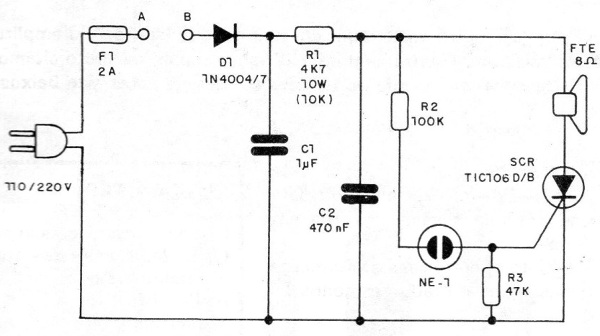
In Figure 2, we have the diagram of our oscillator.
The assembly, based on a small printed circuit board, can be seen in Figure 3.
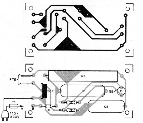
The circuit points A and B are for connection to alarm system relay contacts or even to switches. In the usage part, we will give some suggestions on how to use this oscillator even directly with a sensor connected to the SCR gate.
The SCR used is a TlC106, and either B or D can be used regardless of the network, since the triggering will always occur with a voltage of 80 V in the capacitor and, therefore, between the anode and cathode of this element.
The neon lamp is the common type of two parallel terminals such as NE-2H or equivalent. The diode D1 and 1N4004 (equivalent may be used) if the grid is 110 V or 1N4007 or BY127 if the grid is 220 V.
The capacitor C1 can be polyester, with values ??between 1 and 4.7 uF, and insulation voltage of 250 V or more if the grid is 110 V. For the 220 V grid, the insulation voltage must be 400 V or more.
For C2, we can use ceramic or even polyester types with working voltage of 220 V or more. R1 is a wire resistor whose value depends on the grid voltage. For the 110 V grid, we use a 4k7 x 10 W resistor. For the 220 V grid, its value will be 10 k x 10 W. The other resistors are 1/8 or ¼ W with a tolerance of 5% or 10%.
The input fuse is important for circuit protection and may have values ??in the range 1 to 2 A.
TEST AND USE
To test the oscillator, plug it into the wall outlet and connect points A and B. There should be clear sound. The speaker should be of good quality, at least 10 cm in diameter, for the highest performance.
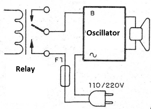
In Figure 4, we have the system connection mode to a common alarm using relay.
In Figure 5, we give a circuit where the oscillator can be used directly as an alarm. Breaking any of the sensors connected to the SCR gate causes the circuit to trigger.
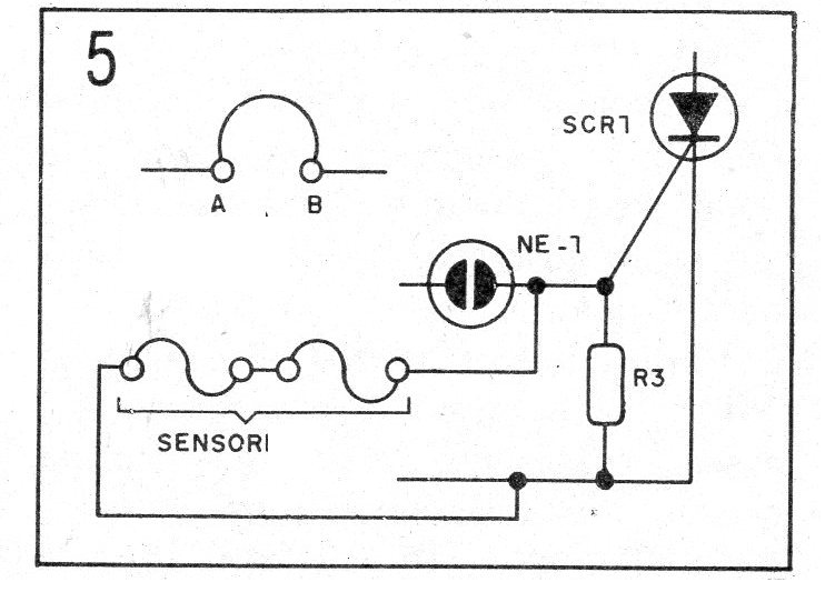
In this system, given the direct operation with the high voltage line, all sensors must be connected by insulated wires. Magnetic switches, such as the reed-switch types, can also be used.
SCR - TIC106B or D - SCR
D1 - 1N4004 or 1N4007 (depending on the network) - Silicon Diode
F1 - 2A - fuse
FTE (Field Effect Transistor) - 8 ohm x 10 cm speaker
NE-1 - NE-2H or equivalent - standard neon lamp
C1 - 1 uF - polyester capacitor (200 V if the grid is 110 V or 400 V if the grid is 220V)
C2 - 470 nF x 100 V or more - ceramic or polyester capacitor
R1 - 4k7 x 10 W (110 V) or 10 k x 10 W (220 V) - Wire Resistor
R2 - 100k - resistor
R3 - 47k - resistor
Miscellaneous: printed circuit board, power cord, wires, mounting box, fuse holder, etc.