
Using two 4046 integrated circuits, which consist of PPL CMOS, this siren produces tones that can be adjusted in modulation and frequency.
Of course, other controls can be added by exchanging other resistors in the circuit (R2 and R4) for potentiometers, or even changing the values of selected capacitors using a switch.
The pleasant tone produced by the circuit can be used for call, warning, toys, sound effect systems and many other applications.
The consumption of the two integrated devices is of the order of 1 mA (without the power stage) and the circuit can be supplied with voltages from 6 to 12 volts. With the step using the TIP31 and 12V supply the current drained from the source will be between 500 mA and 1 A.
HOW IT WORKS
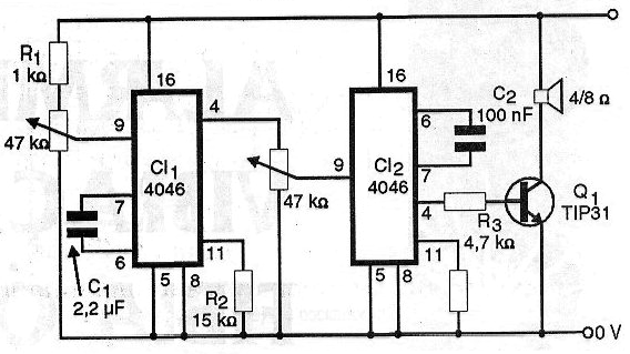
In the 4046 integrated circuit we find a VCO (Voltage Controlled Oscillator or Voltage Controlled Oscillator). These blocks consist of oscillators that operate in the frequency range that extends to approximately 4 MHz, determined by the capacitor connected between pins 7 and 6 and by the resistor between pin 11 and the ground. In our project we have two oscillators, one for the modulation that is determined by C1 and R2 and one for the tone that is determined by C2 and R4. See that we can control these two characteristics by changing the resistors or exchanging them for trimpots or even potentiometers in order to set the central operating frequency of the circuit at other values.
However, as the oscillators are controlled by voltage, we can change their frequency in another way. This is done by trimpots or voltage divider pots.
These potentiometers apply the control signals to pins 9 of the integrated circuits. Thus, for the case of P1 we have the control of the modulation frequency whereas for P2 we have the control of the pitch frequency.
An interesting possibility to obtain an up and down type tone is to add a capacitor, whose value must be obtained experimentally in the range of 47 nF to 1 uF between pin 9 of CI-2 and the ground.
The two oscillators produce rectangular signals. The signal of the second oscillator that is modulated is applied to a power step that uses only a medium power NPN transistor TIP31.
For this stage we have several alternatives.
The simplest possibility is the direct use of a high impedance piezoelectric transducer connected to pin 4 of CI-2.
Other possibilities, shown in figure 1, consist of using a power FET or a power Darlington.

For these steps the power can reach a few watts and the transistors must be mounted on heat radiators.
ASSEMBLY
Figure 2 shows the complete PLL siren diagram.
In figure 3 we have the arrangement of the components on a printed circuit board.
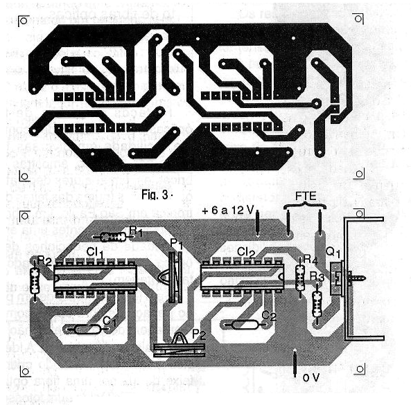
Of course, for studies or experiments, the assembly can easily be made in a matrix of contacts.
For board mounting, it will be convenient to use a socket for the integrated circuits, thus facilitating their exchange or use in case of need. The resistors are 1/8 W or larger and the capacitors can be either ceramic or polyester.
The transistor must be equipped with a medium-sized heat radiator, such as a "U" flat iron, and the speaker must be at least 10 cm in diameter with a power greater than 10 watts.
TEST AND USE
Simply connect the unit to a power supply or battery pack and adjust the trimpots or potentiometers to obtain the desired sound. If this sound is not reached, the capacitors or resistors R2 and R4 are changed.
For battery power, as consumption is high it is recommended to use medium or large units or even if their operation is always done intermittently.
If the circuit is used in the car as part of an alarm, in series with the supply, a fuse of approximately 2 A must be provided.
An interesting possibility for using this circuit is to make a double divider with LDRs instead of the trimpots as shown in figure 4.
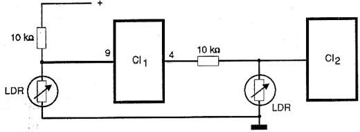
With this feature you can transform the siren into a kind of Theremim of light, in which the tones and modulation produced can be controlled by the shadow of the hands on the sensors.
A third control can be used to trigger the note by activating a digital key, for example, based on a 4066. Of course, in this case, the device, because it is always on, must be powered by a source.
Semiconductors:
CI-1, CI-2 - 4046 - CMOS integrated circuit - PLL
Q1 - TIP31 or equivalent - NPN power transistor
Resistors: (1 / 8W, 5%)
R1 - 1k ohm
R2 - 15k ohm
R3 - 4.7 k ohm
R4 - 2.2 k ohm
P1 - 47 k ohm - trimpot
P2 - 22 k ohm - trimpot
Capacitors:
C1 - 470 nF to 2.2 uF - polyester, ceramic or electrolytic
C2 - 100 nF - ceramic or polyester
Several:
FTE - 4/8 ohms x 10 cm - speaker
Printed circuit board or matrix of contacts, supports for integrated circuits, heat radiator for the transistor, battery support, s power supply or battery connector for the car, mounting box, wires, solder, etc.


