

SIDACs or Silicon Diodes for Alternating Current are semiconductor devices with properties similar to those of the neon lamp and unijunction transistor, however, with a much greater conduction capacity. With them we can design high-power relaxation oscillators, as shown in figure 1.

As we can see, a relaxation oscillator with a SIDAC uses very few components and when it trips, currents of several amps can be conducted in the process of discharging the capacitor.
Ordinary SIDACs can trip at 120 V or 240 V, in which case we can design relaxation oscillators directly powered by the power grid, just as we do in this project.
Note: The SIDAC for this project is 240 V, which means that it will only work on 220 V networks.
The Circuit
The circuit we present is nothing more than a Very High Voltage (MAT) inverter using a relaxation oscillator with SIDAC.
In this circuit, capacitor C1 is charged through R1 and D1 until the SIDAC trip voltage is reached. When this occurs, the SIDAC trips and the capacitor discharges through the primary winding of a high voltage transformer.
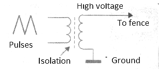
The transformer used in the project is nothing more than a flyback or horizontal output transformer for an old television. On the secondary side of this transformer we have high voltage pulses that can be applied to the fence.
Note that, due to legal requirements, the transformer is completely isolated from the power grid. As a result, the high voltage pulses applied to the fence are low current and have no connection to the power grid (which is prohibited).
The resistor R1 practically determines the device's consumption. Thus, in the 220 V network with a 2.2 k ohm resistor, we have a load current of approximately 0.1 A. In fact, considering that the current is a little lower, as it is not constant. Assuming this value, the device's consumption will be around 20 W.
Assembly
In figure 3 we have the complete diagram of the device.

The assembly, being quite simple, can even be done based on a small terminal bridge. The arrangement of components on this bridge is shown in figure 4.

Readers who wish can create a printed circuit board with the pattern shown in figure 5.

The primary winding of the high voltage transformer consists of 8 to 12 turns of common wire made at the bottom of the ferrite core, as shown in figure 6.
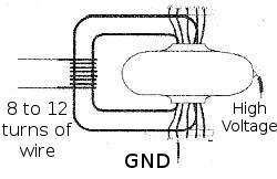
Note that this transformer must be of the old type, which has access to this part of the core so that the primary coil can be wound.
Capacitor C1 is of a special depolarized type for high voltage. The indicated circuit must operate on the 220 V network, since the SIDAC is 240 V. Thus, the capacitor will charge with a voltage of 240 V until the trigger occurs (remember that the peak in the 220 V network reaches more than 300 V) which requires a capacitor with a working voltage of at least 350 V.
The value of this capacitor will determine the intensity of the discharge. Values, between 1 uF and 8 uF can be used.
The resistor must a 20 W 20 W dissipation wire and the reader must not be surprised by the heating of this component in operation.
Test and Use
To try the device, just connect it to the power grid. Approaching a screwdriver to the high voltage terminal connected to one of the low voltage sockets, a spark should occur between 0.5 and 1 cm, as shown in figure 7.
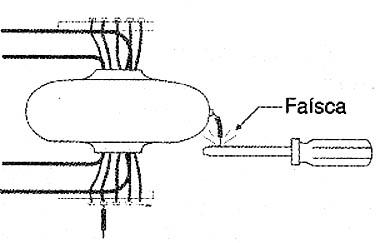
We remember that for every centimeter of spark we have something like 10,000 volts.
The connection to a fence must be made as shown in figure 8.
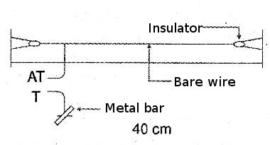
Note that the fence wires are insulated and that there should be an alert notice.
SIDAC - Sidac 240 V
D1 - 1N4007 - silicon diode
R1 - 2.2 k ohm 20 W - wire resistor
C1 - 1 to 8 uF x 350 V or more - depolarized capacitor
T1 - High voltage transformer (flyback) - see text
Several:
Terminal bridge or printed circuit board, wires, solder, power cable, mounting box, etc.


