If you are designing a power application to control a motor, solenoid, or other high current load, you should certainly be considering using a solid-state relay or a contactor.
As we have seen, a solid-state relay or a contactor can be used as static switches, that is, circuits which trigger a load of much greater power from a low current command.
This command can come from a small switch, a reed-switch triggered by a magnet to a more complex control circuit, such as the one that uses a microcontroller.
We have selected in our large collection of circuits some that can be used for this purpose, being called static switches or contactors.
Practical Circuits
1. DC Contactor or bistable static switch
Despite not having isolation, which would be convenient in an application connected to the network, this contactor or bistable power was found in old documentation. However, it can be built on the basis of modern SCRs just as the transistor can be an equivalent.
Capacitor C1 is a depolarized type with a working voltage of at least 100 V, as it is subject to inverting loads. The circuit is given in Figure 1.
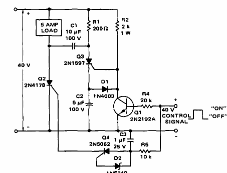
Note that in the original version, the control pulse is of high intensity, but the circuit can be modified to work with pulses generated by a microcontroller.
2. AC contactor or tuned switch
This circuit uses two SCRs in opposition to control the two semicycles of the AC voltage supply. The SCRs must be chosen according to the load current that must be controlled.
In this circuit the load turns on with the positive input and turns off when it is grounded. Note that this input stage can be changed so that the circuit operates with signals from a microcontroller. The circuit is shown in Figure 2.
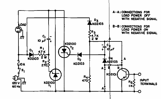
Of course, the SCRs must have good heat sinks.
3. Contactor with two SCRs
This mechanical contactor uses two SCRs to control power loads fed by the power grid. The SCRs can be modern equivalent types, since the configuration was found in old documentation.
Another change would be the use of a reed-switch for control, in which case we can activate the circuit by approaching a magnet. The circuit could then be used as a limit switch or drive in a variety of applications. Figure 3 shows the circuit.
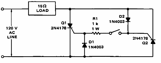
Note that for a 15-ohm load, as indicated, with the original types of SCRs, the current is approximately 8 A.
4. Static switch or contactor with SCR
With a small 5 V reed relay, this circuit can be used as a shield. The power of the load will depend on the SCR used. The circuit is from old documentation.
The SCRs must be provided with heatsinks and diodes must be able to conduct the load current.
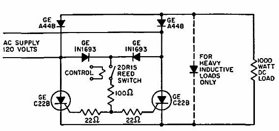
5. DC circuit contactor
This circuit is indicated for the control of a direct current load up to 5 A using a mechanical switch. In this case, a 1 pole x 2 position switch is used.
The SCRs used are from the original old publication. The modern SCRs can be used, depending on the load to be controlled. The circuit is given in Figure 5.
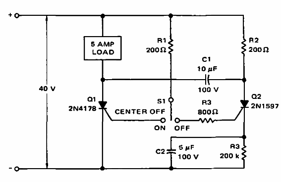
The component values can be changed to the current standards. For example, 220 ohms, 220 k and 820 ohms for resistors and 4.4 uF for C2.
6. Simple contactor with triac
This contactor or power switch with triac, as can also be found on this website, has a very simple configuration. The switch can be a reed type, driven by a magnet, or even a small low current switch.
The triac must have current capacity according to the controlled load and voltage according to the power network in which it is to be used. The circuit is shown in Figure 6.
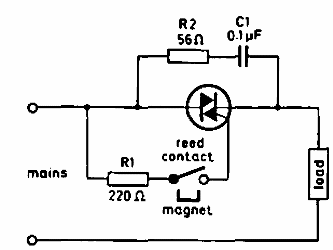
A 5 V low current reed relay can also be used in case of use as a shield.
7. Isolated contactor
This circuit uses an isolation transformer to enable safe operation of loads supplied by the power grid. The isolation transformer is of the type with a 1:1 turn ratio.
In the homemade construction of this transformer, make two coils of 100 turns each in a small ferrite rod 5 to 8 cm long.
The unijunction transistor can be 2N2546. With the control signal, the circuit will generate signals from 600 to 6 000 Hz for the triac to drive. Figure 7.
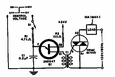
Note that the control voltage can come from a microcontroller, in which case C1 must be set to operate in the desired range of powers.
8. Reversible contactor for motor
This circuit uses two triacs to power a reversible motor powered by the power grid. The circuit is from old documentation, working only for reversible motors with two windings.
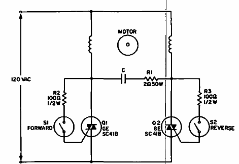
The capacitor C is typically 100 nF of the 400 V depolarized type.
9. Timing DC contactor
This circuit, which can be used as a shield, turns off after the interval determined by the R2 setting and the C2 value. This capacitor can be increased to obtain longer periods.
The capacitor C1 must be depolarized or made with two electrolytes in opposition. See Figure 9 for the circuit.
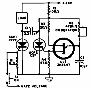
The SCRs must be load dependent and the unijunction can be 2N2646.
Conclusion
In our circuit bench section, the reader can find dozens of circuits which fall into the category of solid state relays or contactors.
It is enough to enter keywords such as power control, solid state relay, power switches, power switches, etc.


