An electroscope is nothing more than an electric charge detector. It indicates whether or not a body has an electric charge and eventually indicates its polarity.
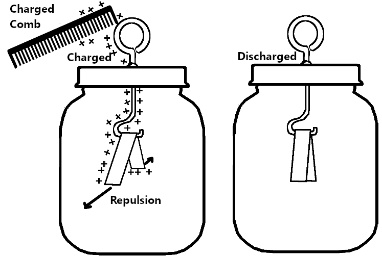
In schools and laboratories, it was common to use an elementary electroscope made of gold foil or eventually an improvised version with aluminium foil. We are talking about the foil electroscope, shown in Figure 1.
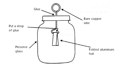
Its operation is simple to explain: When we approach its sensor, a ring, any electrically charged body, the sensor is electrified by induction and transfers the electric charge to the two thin sheets of metal.
As they acquire charges of the same polarity, a repulsion occurs, and they open, as shown in Figure 2.
But, we are in an age of technology and, even in a laboratory for children, it is possible to assemble an electroscope thousands of times more sensitive using electronic components.
We can assemble an electroscope with a field-effect transistor (we also have the project with an integrated circuit, but it will be given at another time). Let's see how it works, starting by explaining what a field-effect transistor is.
The Junction Field Effect Transistor or JFET
The JFET, or Junction Field Effect Transistor, is an electronic component mounted on a small silicon wafer placed in a plastic casing with three terminals.
This device has the structure shown in Figure 3.
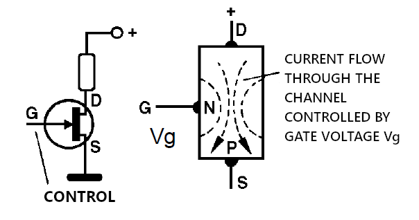
Separated from a material called substrate, which has polarity P, there is an N region, to which a terminal called gate is connected. There are two terminals at the ends of the substrate, drain (D) and source (S).
When we connect a voltage source, no electrical current flows between the drain and the source. The channel formed by the N region is "narrowed".
However, applying a voltage on the gate (G), which is connected to a P region, can widen the channel and thus, electric current flows depending on its polarity.
In other words, we can control the electric current between the drain and the source through a voltage applied in the gate. The gate is, therefore, the input element of the device. The control is made precisely by the electric field formed between the P region and the N region. We say that it is a field-effect transistor.
Since there is a junction between the P and N regions, we say that the component is a junction field-effect transistor or JFET. There are other types of FET.
How does it work in our electroscope?
How The Circuit Works
JFET is extremely sensitive. A small static charge in its gate generates enough voltage to create an electric field capable of controlling the current flow between the drain and the source.
By connecting the gate to a sensor, the electric current between the drain and the source can be controlled if a charged object approaches the sensor. Thus, we can make the transistor work like a switch that turns on an LED when a static electricity charge approaches the sensor.
We will then have a sensitive electronic electroscope.
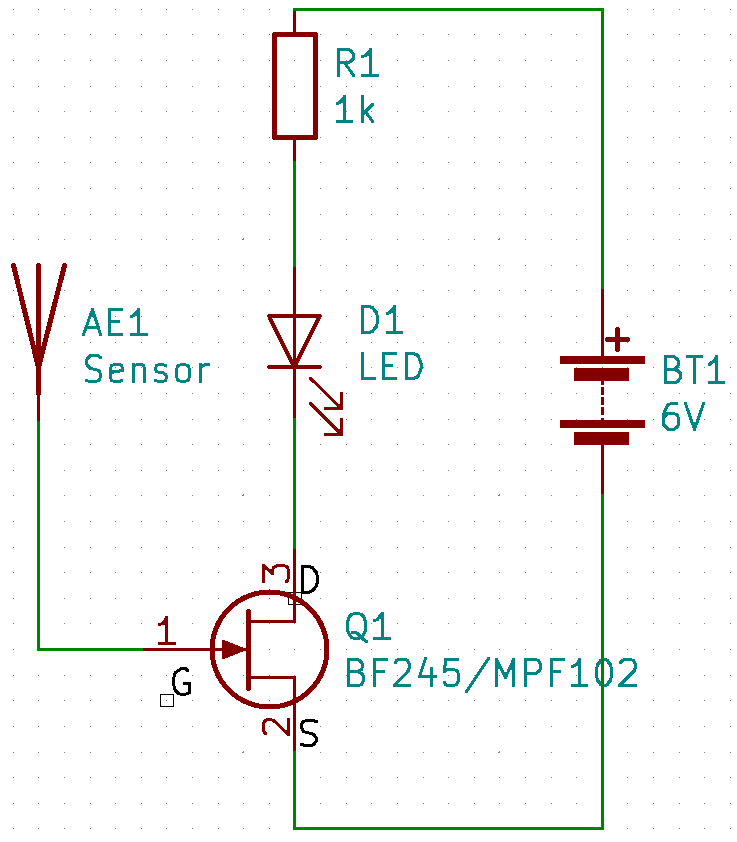
To do it, let's connect the components that make up the circuit, as shown in the diagram in Figure 4.
To power the circuit, we need a power source. In this case, four batteries in a battery holder, supplying 6V. See how we represent this power source: B1.
The LED will be connected in series with a resistor of 330 ohms to 1k ohm, whose purpose is to limit the current in the circuit. The LED can burn out without the resistor if it requires too much current from the power supply. The LED can be of any standard colour.
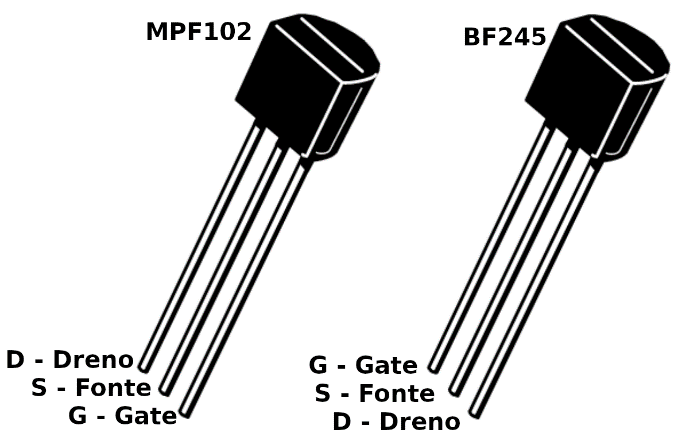
The field-effect transistor we chose is the MPF102, whose terminal layout and appearance are shown in Figure 5.
Note the positions of the drain, source and gate (D, S, G).
You can also use other JFETs like the BF245. But be aware of its terminals layout as it's different, as shown in Figure 5.
In the gate (G), we connect the sensor, a piece of wrapped wire 15 to 20 cm long.
You don't need to strip the wire because when we approach any electrically loaded body, this induces the voltage that goes to the component by approximation and thus controlling it.
Assemble
The best assembly is obtained in a small 170-point contact matrix, as shown in Figure 6.
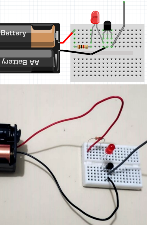
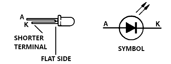
We bend the terminals of the resistor and fit them into the holes indicated. And we fit the transistor and the LED terminals observing the position. See LED position. The shorter terminal is the one next to the drain (D) of the transistor, as shown in Figure 7.
Insert the piece of wire that will serve as the sensor into the hole indicated.
Finally, insert the battery holder wires, observing the polarity by the colours.
The device will be ready to use. The LED can now flash or even light up.
Proof and Usage
Rub a pen, plastic ruler, or another insulating object on clothing and bring it closer to the antenna used as the sensor. When moving the object, the LED should respond with blinks.
If the circuit doesn't work, first check that you haven't reversed the LED. Then check the position of the transistor and make sure the components fit into the suitable holes.
Then do some experiments.
Q1 - MPF102 or BF245 - JFET - see text
LED - standard LED of any colour
R1 - 330 ohms to 1k ohm - 1/4W resistor
B1 – 6V – 4 batteries
Miscellaneous: 170-point (or larger) contact matrix, 4-battery holder, hardwire.

