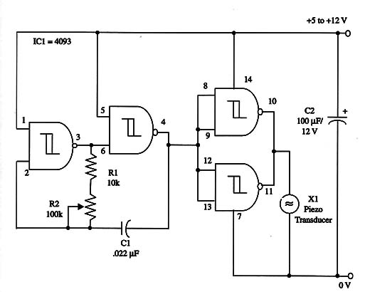
The frequency range can be altered by changing C1. Ultrasonic signals will be produced with capacitor in the 470 pF to 2,200 pF range, and ultra-low frequency signals will be produced with capacitors in the range between 0.22 and 0.47 µF.
A piezoelectric transducer is used in this project, but it can be altered with an additional transistorized driver stage. This stage will drive a loudspeaker, producing a more powerful audio signal.
The circuit can be powered with sources in the range between 5 and 12 V. Only few milliamperes are drained by the circuit, allowing battery operation.
A schematic diagram of the device is shown in Fig. 1.

Frequency adjustments can be made by connecting a frequency counter to pin 10 or 11 (IC 1).
This circuit can be controle by any microcontroller such as the Arduino, PIC and MSP430 acting as a sound Shield.
IC1 - 4093 CMOS integrated circuit
X1 - Piezoelectric transducer or crystal earphone, Radio Shack 273-073 or equivalent
R1 - 10,000 9, 1/4 W, 5% resistor
R2 - 100,000 potentiometer
C1 - 0.022 µF metal film or ceramic capacitor
C2 - 100 µF, 12 WVDC electrolytic capacitor


