Arduino is a development platform which uses small computers (microcontrollers) for the creation of electronic devices. Being an open platform, it is becoming popular and has grown in recent years. Figure 1 shows the development board or board of the Arduino Uno.
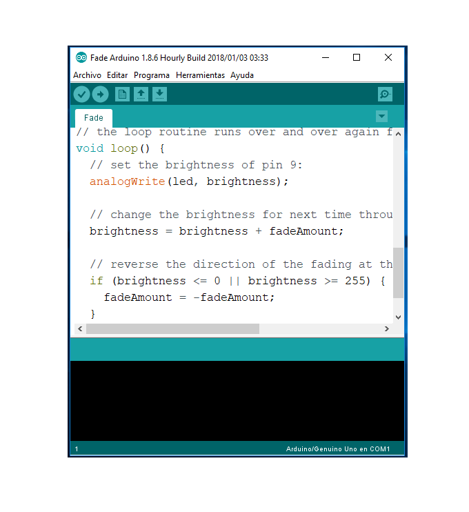
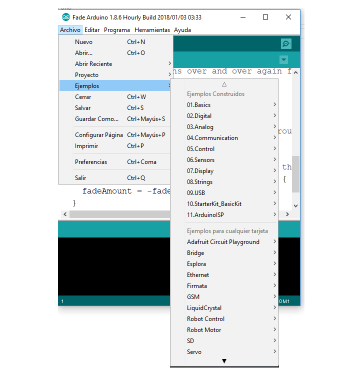
In this article, let's start in the world of microcontrollers in an easy way. To write the code, you need to have the Arduino development IDE installed (see Figure 2), which can be downloaded from the Arduino web page. To begin with, we'll use the sample programs the Arduino development IDE itself has in the menu-> Examples files. See Figure 3.
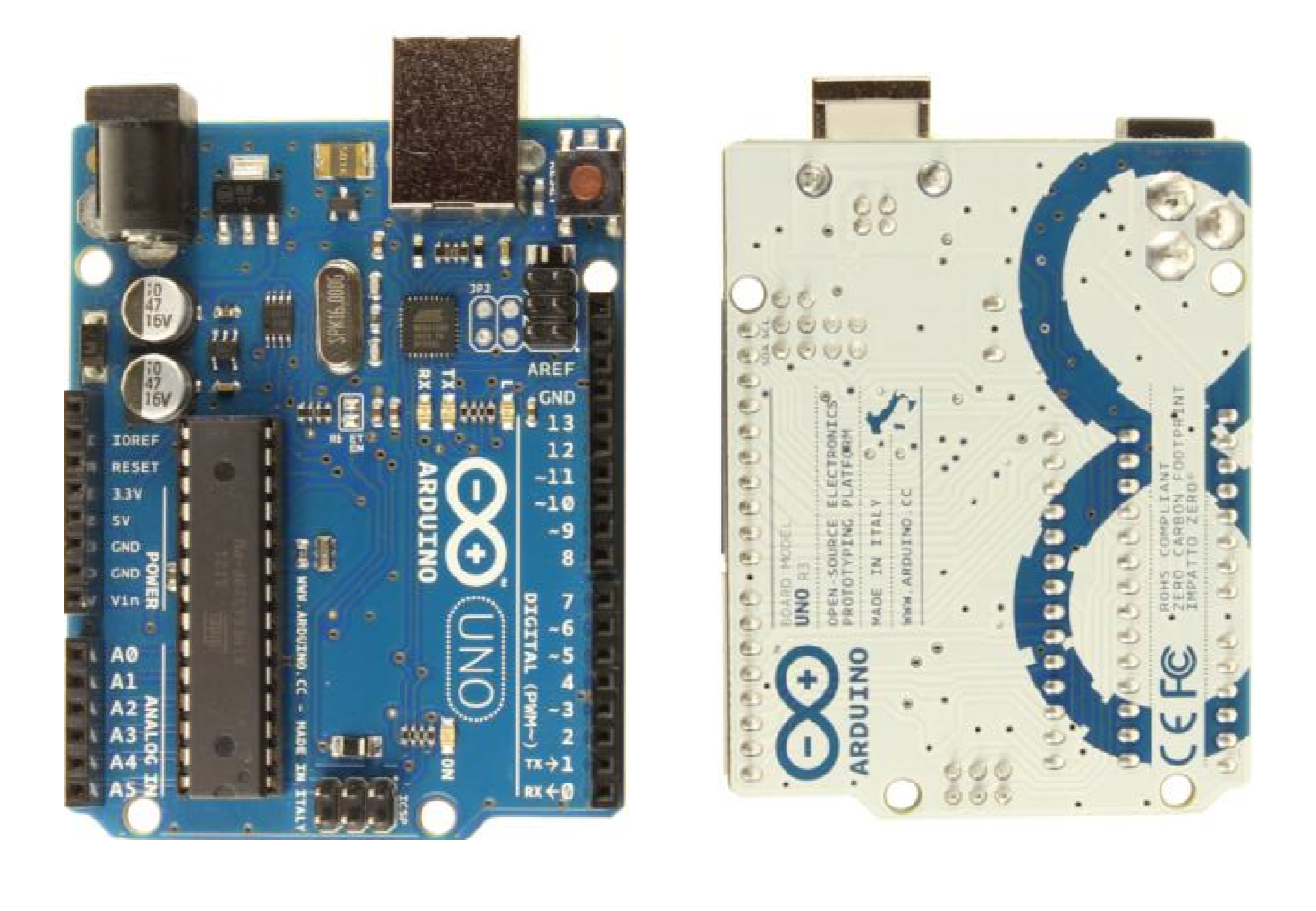
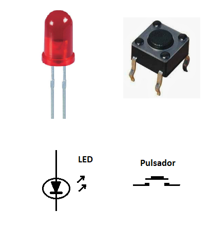
In the following practices, we will use electronic components, such as LEDs and push buttons (see Figure 4). These components will be connected to the input and output pins of the development board. In Figure 5, we can see the location of the input and output pins of the development board. In total, there are 14 pins that are numbered from '0' to '13'. All operate at 5 Volts. Each pin can supply or receive a maximum of 40 milliamperes and have an internal pull-up resistor (disconnected by default) of 20-50 kohms.
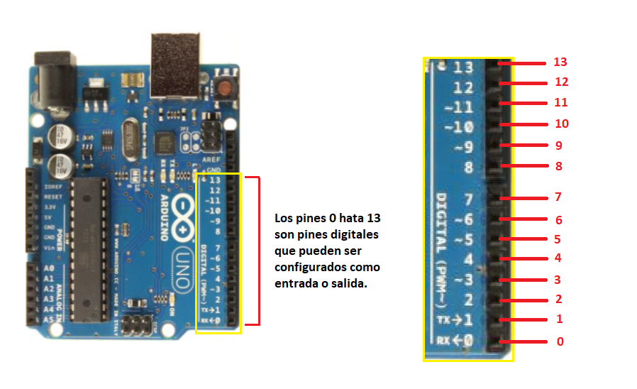
To configure whether a pin is output or input, we will use the pinMode function, which receives 2 parameters. The first is the pin number (from 0 to 13) and the second parameter is if it should be output or input. If it is launched, in the second parameter, we will write OUTPUT and if it is inserted in the second parameter, we will write INPUT. To write a high or low level on a pin configured as output, we will use the digitalWrite function and read the value of a pin, configured as an input, we will use the digitalRead function.
TURN ON / OFF AN LED.
Go to the File Menu-> Examples-> 01.Basics-> Blink. The following code will appear in the IDE:
// the configuration function is executed once you press the reset key or turn on the board
void setup () {
// initialize the LED_BUILTIN digital pin as output.
pinMode (LED_BUILTIN, OUTPUT);
}
// loop function works over and over again forever
empty loop () {
digitalWrite (LED_BUILTIN, HIGH); // turns on the LED (HIGH is the voltage level)
delay (1000); // wait a second
digitalWrite (LED_BUILTIN, LOW); // turn off the LED by making the voltage LOW
delay (1000); // wait a second
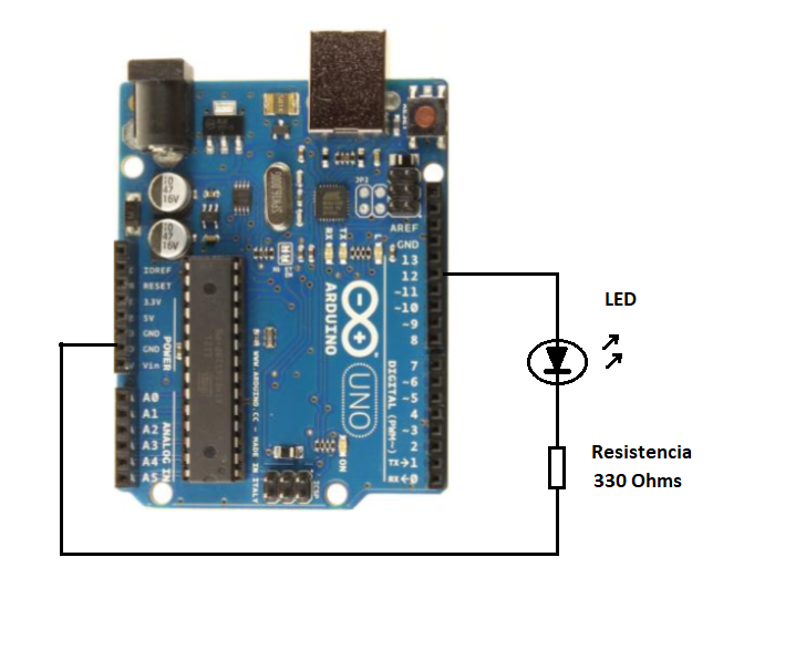
In this example, we turn on and off an LED. The Arduino Uno board has an LED (built-in) connected to the digital pin 13 which, by default, is called LED_BUILTIN. If you want to connect LEDs to other pins, you can follow the electrical diagram in Figure 6. You should declare a constant such as:
counts int LED_APP 12
in case the LED is connected to pin 12. Have changed this number according to the pin where the LED on the Arduino Uno board is connected.
All characters found after '//' are comments and work to indicate and remind us that they make certain sections or parts of a code. In the previous code, there are two functions:
setup ()
loop ()
The setup () function is where the microcontroller is configured and only runs once, when the board is powered by a voltage source or when we perform a reboot. This function is very similar to the BIOS (Basic Input Output Setup) of personal computers. In this function, we program the inputs and outputs of the microcontroller.
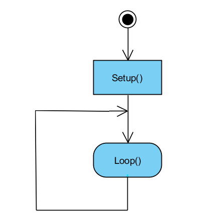
The loop () function, as the name implies, is a loop which repeats itself indefinitely and is where the main program is written. Figure 7 shows the flowchart for the configuration () and loop () functions. We can see the setup () function is executed at the beginning and the loop function repeats itself indefinitely.
The configuration function is:
void setup () {
pinMode (LED_BUILTIN, OUTPUT);
}
Within the setup () function, the pinMode function is called (LED_BUILTIN, OUTPUT); This function tells the microcontroller the LED will be set to output.
Void loop () {
digitalWrite (LED_BUILTIN, HIGH);
delay (1000);
digitalWrite (LED_BUILTIN, LOW);
delay (1000);
}
Within the loop () function, it is called the digitalWrite function (LED_BUILTIN, HIGH); This function writes a logical "1" or a high level on the LED pin. In digital electronics, high levels are represented by a voltage of 5V. The loop () function also calls the delay function (1000); which delays the operation of the microcontroller by the amount of milliseconds specified in the function parentheses.
As in the case of the previous example, we are delaying the microcontroller in 1000 milliseconds or 1 second. Next, we use the digitalWrite function (LED_BUILTIN, LOW); which places a logical "0" or level under the LED pin. In digital electronics, a low level is represented by 0 volts or ground (GROUND). So we have a delay of 1 second.
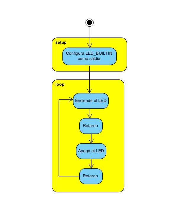
Thus, the program repeats continuously and we can observe how the LED turns on and off continuously. If the parameters of the delay () function are changed; One can see the flicker change in the LED. This program, although basic, is important to understand well, because all programs follow the same rule, however complex they may be. Figure 8 shows the flowchart of the previous example.
CONNECTING A PUSH BUTTON TO THE MICROCONTROLLER
In this practice, we will connect a button to a microcontroller pin configured as a digital input. The sample code can be found in the IDE in the Menu: File->
Example-> 02.Digital-> Button.
// constants will not be changed. They are used here to define pin numbers:
const int buttonPin = 2; // the pushbutton number
const int ledPin = 13; // the number of the LED pin
// variables will change:
int buttonState = 0; // variable to read pushbutton status
void setup () {
// initialize the LED pin as an output:
pinMode (ledPin, OUTPUT);
// initialize the button pin as an input:
pinMode (buttonPin, INPUT);
}
void loop () {
// read the push button value state:
buttonState = digitalRead (buttonPin);
// make sure if the button is pressed. If it is, the STATUS button is HIGH:
if (buttonState == HIGH) {
// turn on the LED:
digitalWrite (ledPin, HIGH);
} else {
// turn off the LED:
digitalWrite (ledPin, LOW);
}
}
At the beginning of the program, we define 2 integer constants, that is, say that these values will not change during program execution. For this, the word const is used, as shown in the following lines of code:
const int buttonPin = 2;
const int ledPin = 13;
In the setup () function, we set pin 13 as digital output and pin 2 as digital input, as seen in the code:
void setup () {
pinMode (ledPin, OUTPUT);
pinMode (buttonPin, INPUT);
}
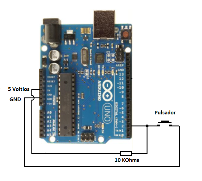
The pinMode function (ledPin, OUTPUT); informs the microcontroller the led pin (13) will be configured as an OUTPUT and pinMode (buttonPin, INPUT) function; tells the microcontroller the buttonPin (pin 2) will be configured as a digital input (INPUT). The hardware for this example is shown in Figure 9 where we can see that the button passes on pin 2. It is necessary to connect a resistor from 10 kOhms to 5 volts (pull-up), to polarize the input to positive, when the button is not pressed.
We also declare a variable value button, which means its value or content will be modified by the program. The following line of code shows and declares the variable for the compiler:
int buttonState = 0;
The code for the loop () function in this example is:
Empty loop () {
buttonState = digitalRead (buttonPin);
(buttonState == HIGH) {
digitalWrite (ledPin, HIGH);
} else {
digitalWrite (ledPin, LOW);
}
}
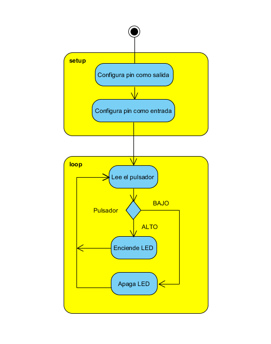
In the loop () function, we use the digitalRead function (buttonPin); to read the push button of the digital input button and store this value in the buttonState variable. The code then checks to see if this value is HIGH (HIGH) for which we use the if statement (buttonState == HIGH). If the value is high, we will execute the digitalWrite function (ledPin, HIGH); or the buttonState button is down, the digitalWrite function will be executed (ledPin, LOW); Thus, when reading a digital input, we can control the outputs (actuators) or execute some other code. Figure 10 shows the flowchart for reading the button.
PWM TO INCREASE AND DECREASE THE LED LIGHT INTENSITY
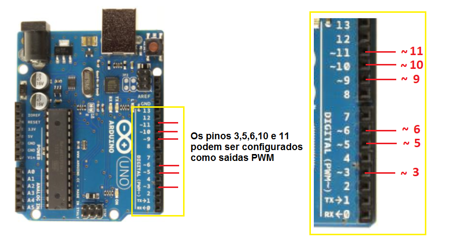
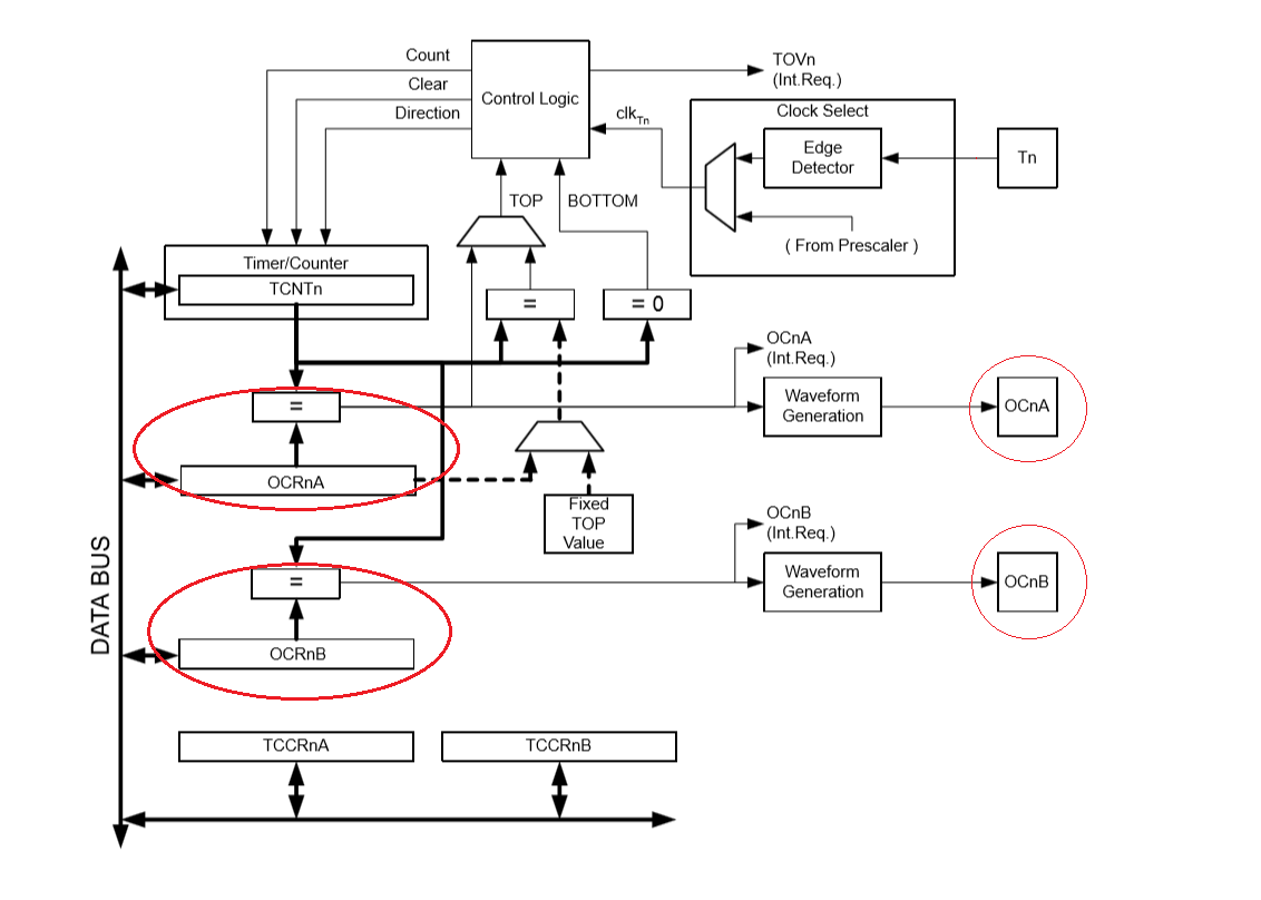
Pins 3, 5, 6, 9, 10 and 11 of the Arduino Uno board can be used as analog PWM outputs. In total, there are 6 pins with PWM on the Arduino Uno board. Figure 11 shows these pins. Note that on the board, these outputs are marked with the ~ symbol before the number, indicating the PWM outputs. The ATmega328P microcontroller used on the Arduino board has 3 timers. Each timer has 2 output comparison modules which are typically used to generate PWM signals. In Figure 12 we can see the Microcontroller Timer 0.
The sample code for this practice can be found in File-> Examples-> 01.Basics-> Fade. The main idea is to increase and decrease the luminous intensity of the LED using a PWM (Pulse Width Modulator). The code in this example is:
int led = 9; // the PWM pin where the LED is connected to
int brightness 0; // how bright is the LED
int fadeAmount = 5; // how many points to disappear on the LED
// the configuration routine is executed once when you press reset:
void setup () {
// states that pin 9 is an output:
pinMode (led, OUTPUT);
}
// the loop routine runs over and over again forever:
void loop () {
// sets the brightness of pin 9:
analogWrite (led, brightness);
// change the brightness to next time through the loop:
brightness = brightness + fadeAmount;
// reverses the direction of fading at the ends of fading:
Datasheet of if (brightness <= 0 | brightness> = 255) {
fadeAmount = -fadeAmount;
}
// wait 30 milliseconds to see the darkening effect
delay (30);
}
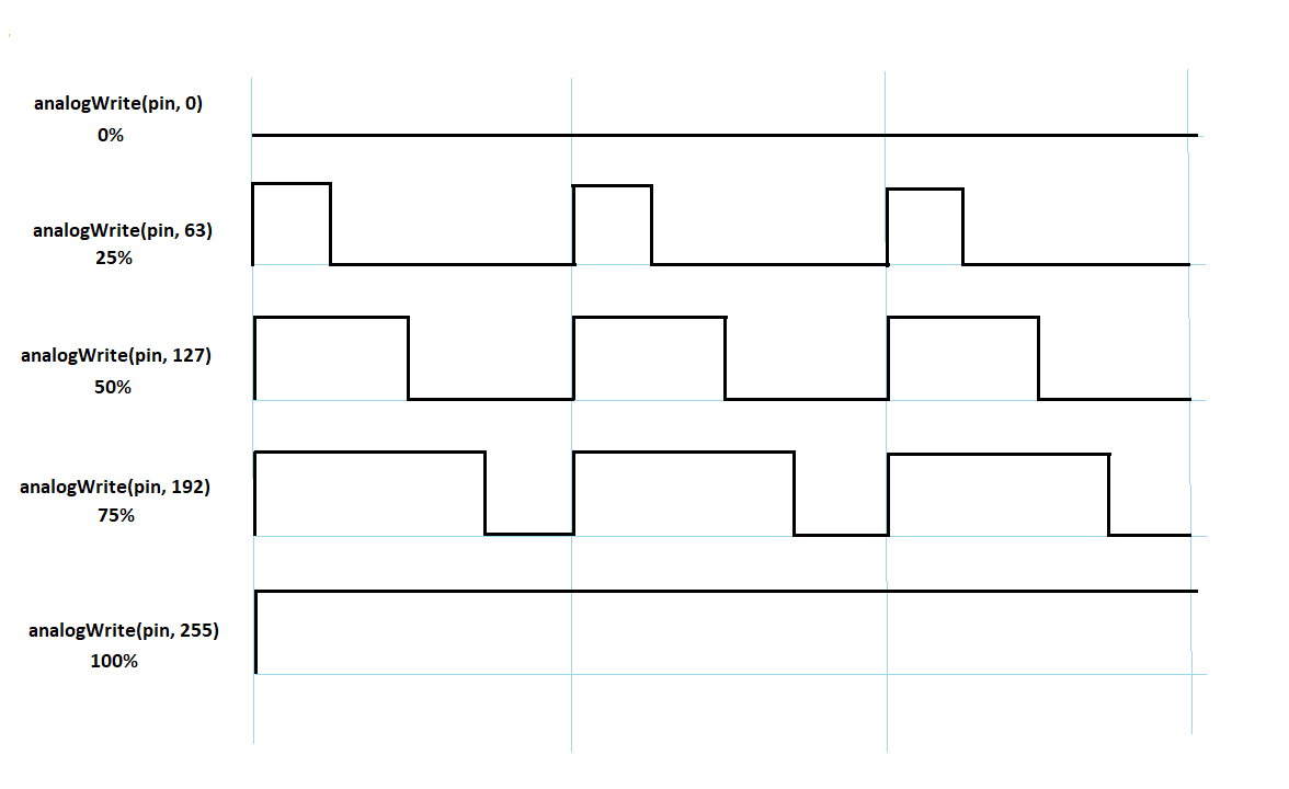
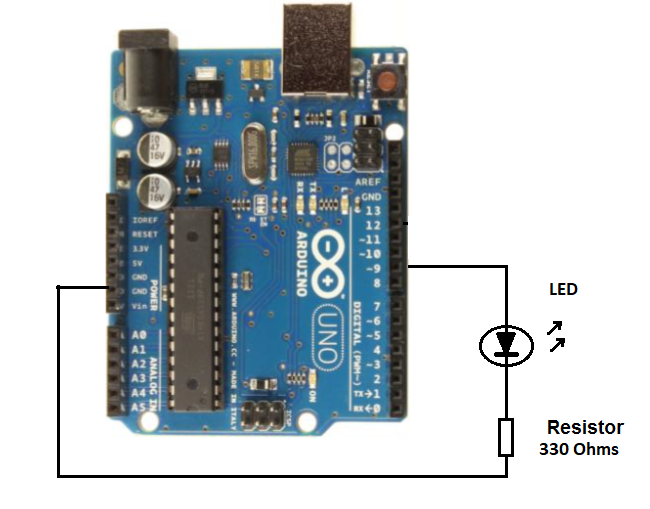
PWM is a pulse width modulation technique which can be used to control current flowing through a circuit very similar to the potentiometers in a dimmer. To do this, we can use the analogWrite function which receives 2 parameters. The first parameter is the pin to be controlled and the second parameter is the amount of time the pin will remain at the high level (ON). Figure 13 shows how the second parameter acts on the pin it is controlling. As the pulses are repeated rapidly (approximately 500 Hz), the human eye does not notice its change, but as the pulse width varies, it gives the optical sensation of increasing and decreasing the intensity of the LED. The hardware required for this practice can be seen in Figure 14. Note that the LED is connected to pin 9.
At the beginning of the program, we declare 3 variables as follows:
int led = 9;
int brightness = 0;
int fadeAmount = 5;
The led variable is the pin on which we are going to connect the LED. The brightness variable stores the brightness value of the LED and the fadeAmount variable is used to change the brightness.
In the setup () function, we configure the LED pin as an output for which we have the following code:
void setup () {
pinMode (led, OUTPUT);
}
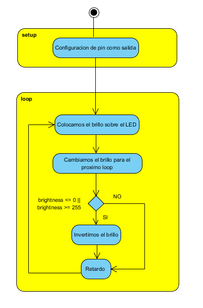
In the function loop () we use the function analogWrite (led, brightness); to place a pulse width value on the PWM output. Next, we add a fadeAmount to the variable brightness to increase its value in scalar form. Then we detect whether the variable brightness is greater than or equal to 255 and invert the fadeAmount variable to reverse the brightness effect. Finally, we give a 30-millisecond challenge. In Figure 15, we can see the flowchart of this practice. The code for the loop () function is as follows:
Void loop () {
analogWrite (led, brightness);
brightness = brightness + fadeAmount;
Datasheet of if (brightness <= 0 | brightness> = 255) {
fadeAmount = -fadeAmount;
}
delay (30);
}
Thus, by means of lines of code, we can interact with the outside world, that is, we can read signals (inputs, sensors) and we can evaluate these values to make decisions about outputs, usually called actuators. Imagination is the indicator which you can use these resources to create designs and electronic devices.