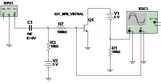
In this simulation we show how to implement a test circuit for BJT transistores. In the simulation we show a NPN transistor, but if all polarities of signals are changed, NPN transistors could be tested. The signal source is adjusted to a 1 kHz x 10 kHz sinusoidal signal. See that the circuit has two power supplies. Figure 1 shows the circuit.

Figure 1 – The circuit for test
Download the simulation files and Netlist - click here (msb0070.zip)