This circuit show the performance of a GraetzBridge or Diode Bridge usedin full-wave rectifers. The circuit applies a 60 Hz x 10 Vpp signal to the bridge showing in the oscillloscope of the Multisim Blue the waveshape of the rectifier voltage. See the adjustments for the function generator and the osclloscope.

Figure 1 – Test circuit
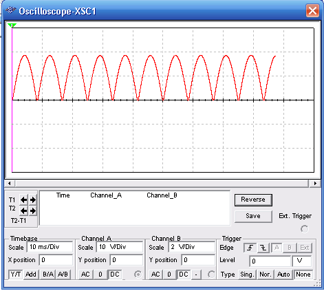
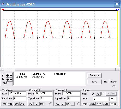
Bellow we have the display for a perfect bridge and the display for na open diode or missing diode.
To download the simulation files and Netlist - click here (msb0007e.zip)