IGBTs are widely used in frequency inverters, power controllers, switched sources and DC/DC converters. These components have hybrid features, with an isolated gate as a MOSFET and junctions between the collector and emitter as a bipolar transistor.
One of the most common tests for an IGBT test is the dynamic test of charging a 40 to 100 W bulb in its collector and powering the circuit with a voltage of up to 100 VDC.
With the gate connected to the emitter of the transistor, it must remain in the cut and with this the lamp is off.
By connecting the gate to the collector (which must be done with a 10 k ohm resistor), the transistor will saturate and the lamp will light up. This dynamic procedure is shown in Figure 1.
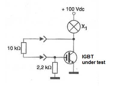
If the lamp remains on, both the IGBT is shorted, and if it stays off, the IGBT is open. The reader must be aware of the maximum voltage that can be applied between the gate and the emitter of the transistor, which is generally 20 V.
If the test is made with higher voltages, the voltage applied to the gate must always be less than 20 V.
However, a similar test can be done with an analog meter and even with some types of digital multimeters which have enough test voltage to saturate it when placed on resistor scales or diode test.
For this purpose we can initially perform a short-circuit test, as shown in Figure 2.
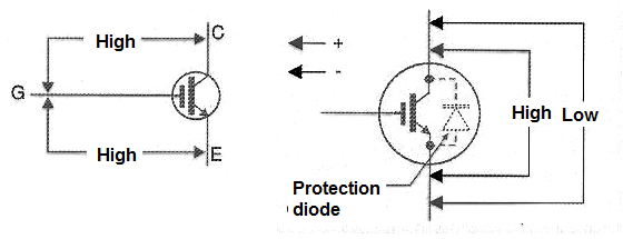
We initially measured the resistance between the gate and the collector terminals and then between the gate and the emitter.
In both measurements, we must have readings of high resistances. By high resistance, we mean values above 10 M ohms.
If either of the measurements has a low resistance or even average reading (between 10k and 1M ohms), the IGBT is destroyed by short or even excessive leakage. If it passes this test, we measure the resistance between the collector and the emitter.
In one sense, it must be high and the other low, because we must consider the protection diode that these components have, as shown in Figure 2.
A low resistance reading on both measurements indicates a short IGBT and a somewhat low resistance reading where it should be very high (between 10k and 1M) indicates a leaky component. In both cases, the component should not be used.
Depending on the battery voltage of the multimeter, a relatively simple switching test can be performed. For this, we use the connection of Figure 3 with the multimeter in an intermediate range of resistors.
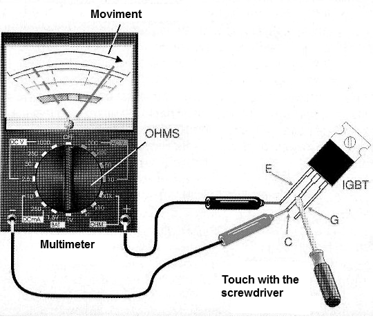
By touching a screwdriver or bridging the gate (g) and collector (C) of the transistor, it must switch.
This will cause the resistance to drop from a very high value to a lower value depending on the characteristics of the test IGBT and the meter itself.
However, it is necessary to take into account that the internal battery of some multimeters does not have enough voltage to make the component conduct.
To be sure this test applies with the multimeter available, it will be interesting to try with an IGBT that we know is in good condition.
One way to test an IGBT with the multimeter in case the direct test described is not possible is shown in Figure 4.
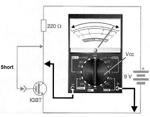
A 9 V battery or even a larger voltage source (20 V) provides the voltage required to polarize the component and thus a boost current reading can be made in the case of a good component.
IGBT Test Circuit
There are simple ways to test an IGBT. However, with the use of a function generator and an oscilloscope, we can go further and determine the characteristics of the component under test.
In Figure 5, we show a circuit for this purpose. This circuit fits most common IGBTs and is simple to deploy. We can also use it with didactic purpose to demonstrate the characteristics of this component.
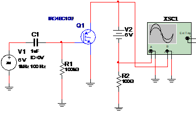
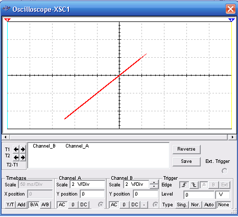
In this circuit, the oscilloscope is set to the B/A function, i.e., Y-axis signals as a function of the X-axis and the typical sensitivity of the two axes is 2 V/div.
See we also need a 6 V power supply for the tests. The signal generator is set to produce a 1 kHz signal modulated in amplitude at 100 Hz with a depth of 1 unit.
In Figure 6, we have the signal that must be observed for a good IGBT in the simulation made in Multisim.
The values of the components used can be changed as well as the test signals, depending on the characteristics of the tested IGBT.


