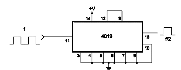
This circuit turns on and off from pulses applied to the CLK input. The output 0 goes to the “’1" logic level with the first transition of the input impulse from positive to negative. The circuit can also be used as a frequency divider since a square wave applied to the input will correspond to another square wave in the output, but with half the frequency. The circuit and waveforms are shown bellow. Since the 4013 has two D-type flip-flops in the same package, the other can be used in the same or other functions. The numbers given in the figure correspond to one of the flip-flops.


