
Drawing from his experience as an educator with more than 15 books published in the United States and many others in the rest of the world (mainly in his country, Brazil, where he has more than 150) the author selected some projects of his site (www.newtoncbraga.com.br) that can be used to teach engineering.
They are ideal projects to follow the new rules of science, technology, engineering and mathematics (STEM) teaching that adapt to elementary and middle schools. Teachers and students will be able to execute these projects with ease.
Many of them use scrap material, while others make use of traditional material (discrete components) that can be easily manipulated and understood.
Assemblies can be made either using solderless boards or, in a more rudimentary version, a terminal strip.
Components also can be brought at Mouser Electronics (www.mouser.com).
Simplified Telegraph
An old speaker, one or two (even weak) cells, a file and wires is all that the reader needs to set up a telegraphic communications system.
To each shave of the wire in the file at X1, which acts as the manipulator, the speaker sends a signal. A long shave will be a dash and a short shave will be a dot.
Combining dots and dashes according to the Morse Code, we can send messages at distances up to 100 meters. Search the Morse Code for information on the Internet.
The basic system has two wires, but we can save the wire if the T-points are connected to the ground, ie two metal rods buried in damp ground. In this case, the "return" of the signal will be made by the earth, which is conductive.
This saves yarn, as we only need a conductor to connect the stations. In figure 1 we have the complete diagram of the apparatus.

Figure 2 shows the aspect of the device ready to be used.

B1 may be formed by one or two small, medium or large cells. The speaker can be of any type and size. The wire can be any thickness provided it is insulated, so that no losses occur. The file is of the flat type of any size.
To use, just rub the end of the wire into X1. There should be sound emission on the speaker. Do not let the cord touch X1 when the appliance is out of use or out of use as this will cause the batteries to drain quickly.
Parts list
B1 - 1 or 2 cells - see text
X1 - File / wire - improvised manipulator
FTE - 4 or 8 ohms - speaker of any size
Miscellaneous:
Loudspeaker, wires, solder, etc.
THE SHOCK BOMB
This is a harmless joke for those who like to shock others. A loaded capacitor, secure at the right time, gives a good shock to the unsuspecting.
You load a capacitor and fold its terminals so they are in an appropriate position. When your friend is distracted, you yell "Hold it”! And throw the capacitor. Of course, in a reflex impulse, it will hold the capacitor and then the surprise: a good discharge of a few hundred volts. The charger circuit consists of only one diode and one resistor, where the capacitor is connected for a few seconds to the charge.
The capacitor can be of the polyester type with values between 100 nF and 470 nF, taken from out of use appliances, and must be specified for a working voltage (other than the one it charges) of at least 400 V. Before using the capacitor, however, you need to know if it is good. To do this, load it and touch one terminal on the other. If there is a spark it is because the capacitor has retained the charge and is in good condition.
Paper and oil capacitors from old appliances can also be tested, but usually time and humidity will keep them from holding more charge. The retention time of the charge is short, ranging from 1 to 2 minutes for the older ones and up to about 1 hour for the new ones.
Once the game is played and the discharge occurs, the capacitor needs to be charged again. Never leave the charging terminals against each other as this will heat the resistor and may cause it to burn. If the resistor burns or overheats when the load is present, the capacitor is shorted.

Parts list
D1 - 1N4004 (110 V) or 1N4007 (220 V) rectifier diode
R1 - 1 k ohm x 2 W - resistor (brown, black, orange)
C1 - 100 nF at 470 nF - capacitor (see text)
The World's Smallest Radio
This radio is so small to mount it up in a matchbox. Of course, due to the lack of amplification steps and the simplicity of the circuit, it presents some drawbacks that well demonstrate the difficulties encountered by radio pioneers.
Listening is only possible with a sensitive headset and you will still need to use a very long antenna, at least 10 meters long. This is because the energy that produces the sound in headphones is the very energy captured by the antenna, which should be as large as possible.
However, in locations where there are strong AM stations, we can get a good listening of stations as long as they are not too far away.
It is, in fact, a modernized version of the old galena (crystal) radios used by our ancestors in the early days of the radio. In this version the crystal of galena is replaced by a diode of germanium. In figure 4 we have the complete diagram of the radio.

The clips A and T are connected to an antenna and earth. Earth can be any large metal object that has contact with the ground. The antenna is a conductive wire that can be wrapped, stretched. In figure 5 we have the receiver assembly.

The coil L1 is formed by 100 turns of enamelled wire AWG 28 to 30 in a cardboard tube into which a small ferrite core can slide. This core can be obtained from IF coils of old radios. The movement of the ferrite makes the tuning of the station. The capacitors C1, C2 and C3 are ceramic and the diode can be 1N34 or any germanium equivalent.
It is important to note that the handset must be crystal or a high impedance ceramic capsule. Most common headphones of the type used in MP3, Walkman and other devices are of low impedance.
In figure 6 we have the suggestion of assembly in a small box.

Material list
L1-Coil - see text
D1- 1N34 - germanium diode
C1- 10 pF-ceramic capacitor
C2- 100 pF-ceramic capacitor
C3- 10 nF- ceramic capacitor
J1- Jack to the phone
Miscellaneous: box for mounting, ferrite stick, enameled wires, crystal earphone, etc.
Controlling the Brightness of an LED
The intensity of the current flowing through an LED determines its brightness, that is, the amount of light it produces.
The resistor we connected in series with the LED limits the current that circulates through it being calculated as a function of the battery voltage as the current we want in the circuit. We can, however, vary the current in the circuit with a component called a trimpot.
When we rotate or adjust the axis of the trimpot, it changes of resistance and with that we can control the current that passes through the circuit. In our experimental design we will connect the trimpot in series with the LED, but we will keep the resistor to determine the maximum current, and with this we can adjust its brightness.
Assembly
In figure 7 we have then the diagram of the brightness control that we will mount in a solderless board or protoboard.

The arrangement of the components in a 170 point solderless board points is shown in figure 8.

On assembly, observe the position of the LED, because if it is inverted, it will not light and we will not have the control.
To use the circuit with a small screwdriver, and carefully, turn the potentiometer or trimpot setting and see what happens to the brightness of the LED.
Another way of doing the same circuit is to connect the free terminal of the potentiometer to the central terminal, as shown in figure 9.

In the configuration in which we use only two of the trimpot terminals or we join two of them, we say that this component functions as a rheostat.
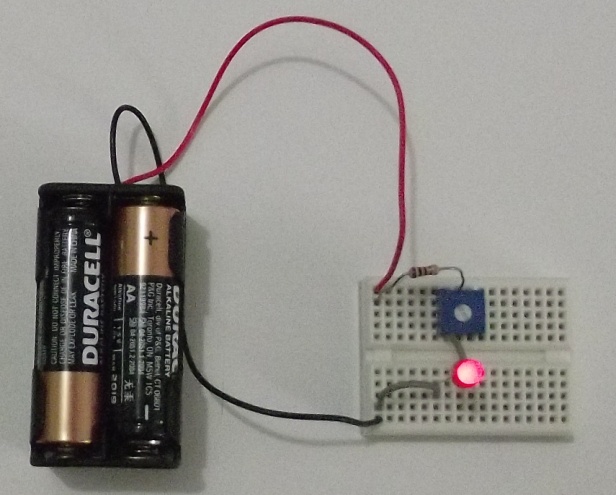
In figure 10 we have the basic assembly photo.
Material
LED – Common LED
R1 - 1 k ohm - resistor - brown, black, red
P1 - 10 k ohm trimpot
B1 - 6 V - 4 small batteries
Miscellaneous:
Solderless board, battery holder, wires, solder, etc.
Quiz:
- Does the higher LED brightness occur when the trimpot is in the higher or lower resistance position?
- What is the function of the trimpot in the circuit
- Why, although the trimpot represents a resistance, we still need to use R1?
A Touch Sensor
The resistance of a person's skin is very high, not letting enough current pass to light an LED. However, this current can be amplified by the transistor and thus acquire enough intensity to trigger an LED.
In our experiment, we will use two wires that hold between the fingers, allow to pass a very low current to the base of the transistor. This current is amplified and turns on the LED. Just hold the ends of the wires as the LED lights up.
One type of sensor that can be used in this circuit is the humidity or water sensor.
Put the tips of the wires used as a sensor in an empty glass. When you pour water into the cup and it reaches the ends of the wires, the LED will light up. Many leakage, flood, and waterwell alarms use this type of sensor.
Assembly
In figure 11 we have the circuit used in the experiment.

The assembly in the solderless board is shown in figure 12.

Be careful with the transistor position, LED position and polarity of the batteries in the assembly. Any inversion can cause components to burn.
Note that the brightness of the LED varies when we tighten the wires more and with that the electric resistance decreases, increasing the current in the transistor.
Used material:
Q1 - BC548 - NPN transistor
LED - LED common
R1 - 1 k ohm - resistor - brown, black, red
R2 - 100 k ohm - resistor - brown, black, yellow
R3 - 22 ohm - resistor - red, red, black
B1 - 4 batteries
Miscellaneous:
Solderless board, support of batteries, wires, etc.
Quiz:
- What happens to the brightness of the LED if your hand is very dry and thus has a very high resistance?
- Will the LED light up if we put wire in a small piece of metal?


