The fact that we have a remote control does not necessarily mean that there should not be any physical connection between the controlled object and the controller.
In some cases the use of a physical mean may be advantageous, especially if the controlled object is fixed and the controller does not require high mobility either.
It is the case of remote systems of opening garage doors from inside the house controls, or even signaling.
In Figure 1 we show, in a simplified form, a system that can perfectly make use of common connection wires between the control station and the commanded object.
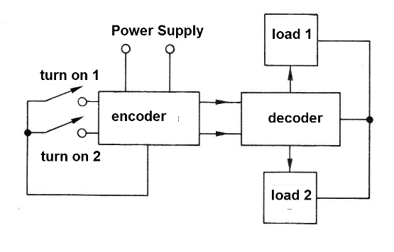
While for most readers a control of this type is more than obvious, there are still interesting solutions which deserve to be analyzed, as they imply both greater efficiency and even great material savings.
In this article we will try to address some of these seemingly simple solutions, but which are very interesting.
SIMPLE CONTROL THROUGH TWO WIRES
A simple idea of ??remote control of two lamps using only a pair of conductors, and perhaps already known to many readers, is shown in Figure 2.
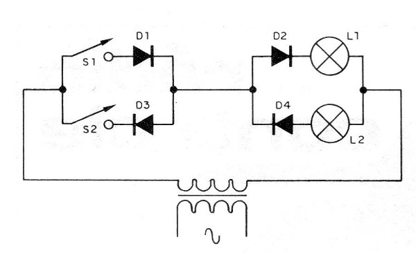
What we have is a transformer which provides an alternating voltage for the power to the circuit. The winding voltage of this transformer must be in accordance to the lamps to be controlled.
Four diodes are then used, polarized on a par with the lamps to be controlled.
When the switch 1 is closed only diodes D1 and D2 conduct, and the lamp L1 lights up. When the switch 2 is closed only the diodes D3 and D4 drive and the lamp L2 lights up.
This circuit can perfectly be used in the control of two DC motors, in which case we add the capacitors C1 and C2 whose purpose is to allow a full power operation, even with the conduction of half of the semiconductors. (Figure 3)
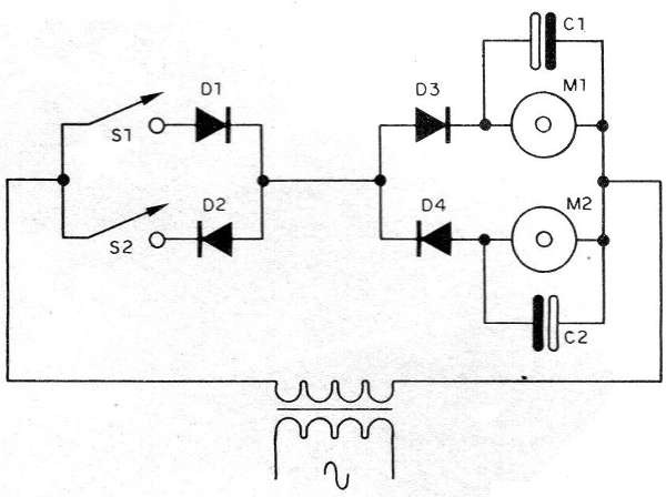
The value of the capacitor must be the greater the higher the current of the motor, being experimentally obtained so that the voltage at its ends corresponds to the voltage that the motor must receive at its maximum.
In Figure 4 we now see the circuit used in the triggering of two relays, in which case loads of different natures can be controlled, since their circuits are completely independent.
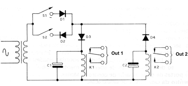
The voltages of the relay coils must be in accordance to the used transformers and again we find the capacitors which help in the stability of their action.
For a 12 V transformer, for example, with a 500 mA secondary relays of up to 100 mA of coil can be used.
The assembler of this system should keep in mind that, operating with low voltage, the influence of the resistance of the wire becomes greater, which limits its length. For a voltage of 12 V, the maximum length with a common wire is around 20 meters.
Turning to an electronic sophistication now, we give in Figure 5 the circuit of a double control with continuous graduation, that is, a pair of remote dimmers.
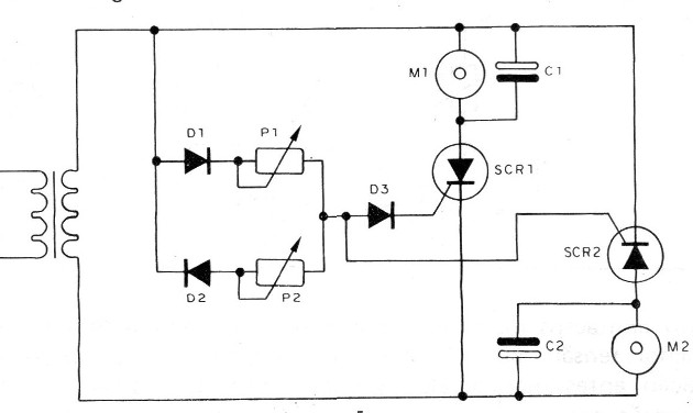
Two common diodes are used in the transmitting station and, instead of the switches, potentiometers from 100 to 220 k, according to the desired speed range and the voltage of the transformer.
In the receiver, instead of the diodes, SCRs of the type MCR106 or TIC106 are used with operating voltages of 50 V.
The capacitors C1 and C2 determine the delay in the firing of each SCR as a function of the power phase and with that the portion of each half-cycle conducted.
When the parcel is larger, the speed is greater.
The values of these capacitors depend on the supply voltage of the circuit and can be between 100 nF and 470 nF.
We recall that SCRs conduct only half of the half-cycles of the power supply, but this can be corrected by using a convenient capacitor in parallel with the loads.
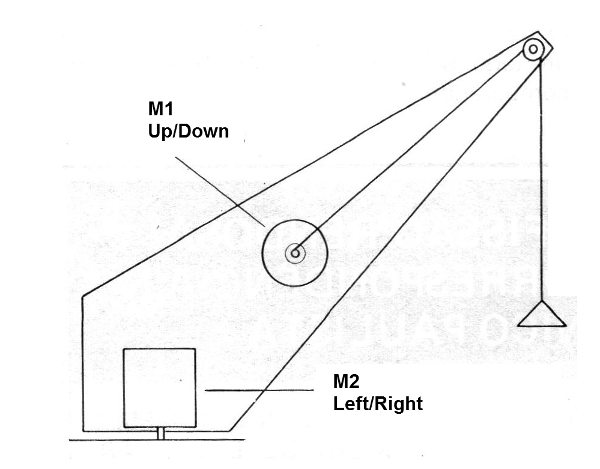
One suggestion of use for this circuit is to make a motor rotate in one direction with one control and in the other with the other control, in which case one can have the opening and closing of a door, or in a mockup the elevation and descent of a crane, as suggested in Figure 6.
Readers must have already felt that many designs can be developed from these relatively simple circuits.
MORE CHANNELS
For the case where it is desired to control more channels with only two interconnecting wires between the stations,there are solutions.
In Figure 7 we have a suggestion which can work as a starting point for a more complex project.
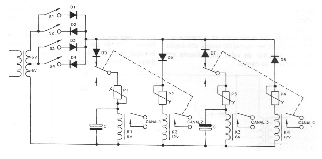
What we have is the expansion of the initial system of two channels with two diodes, adding scaling to the relay drive. With this feature we move from 2 relays to 4.
The operation of this system can be analyzed as follows:
At the transmitting station we have a two-voltage transformer, so that in the receiver we use relays with two different operating voltages.
The ideal operating point of each relay can be adjusted through a trimpot, since the coil currents are small.
In the low voltage relay a delay capacitor is also used, the purpose of which will be explained.
When the switch, which activates the low voltage relay, is pressed it closes its contacts with a short delay and turns on the load circuit.
This small fraction of a second delay is not great enough to be perceived, but it is important, as we shall see.
Now, if you turn on the switch which brings the most voltage to the circuit, the two relays should close their contacts, since the relays do not operate through ranges, but by minimum values.
However, because the low-voltage relay is provided with a delay circuit, the higher-voltage relay closes first, and thus having multiple contacts, it shuts off the low-voltage relay, or rather, cuts off its power even before it closes.
With the higher voltage, only the higher voltage remains active.
Of course, this system does not allow more than two relays to be triggered simultaneously, and these two relays must always be those corresponding to opposite phases.
One possibility of expansion of this circuit for a greater number of channels can be imagined by the reader with the use of electronic comparator circuits.
In this case, the number of channels will only be limited by the distinguishing ability of the comparators.


